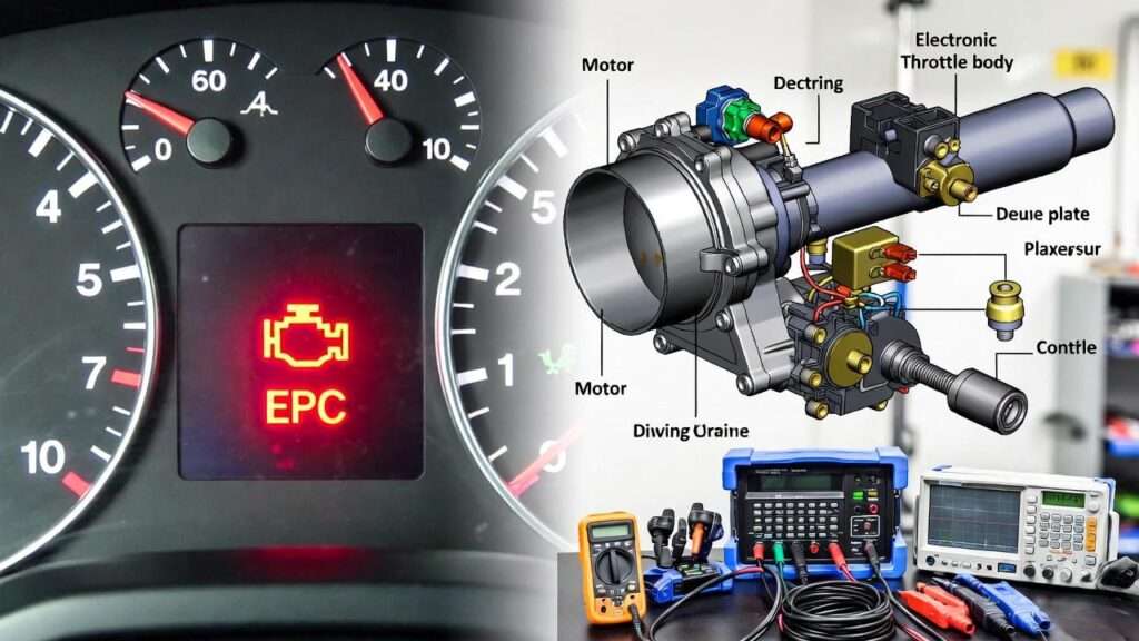
Picture this: You’re loading up your trailer for a long-haul trip—tools, equipment, or family camping gear secured—only to discover your brake lights aren’t working, turn signals are crossed, or electric brakes feel weak and unresponsive. In that moment, a simple electrical fault turns a routine tow into a dangerous, expensive headache. Poor 7 pin trailer wiring is one of the leading causes of towing-related incidents, from failed signals that confuse other drivers to intermittent brake controller issues that compromise stopping power.
As a mechanical engineer specializing in automotive systems and towing dynamics with more than 20 years of experience—including designing electrical integrations for commercial fleet vehicles and conducting field diagnostics on heavy-duty trailers—I’ve seen these problems repeatedly. The good news? 7 pin trailer wiring follows clear, standardized principles that, when understood and applied correctly, deliver reliable performance every time.
In this in-depth guide, we’ll break down everything you need to know about 7 pin trailer wiring: from the engineering fundamentals and SAE J560 standards to detailed pinout diagrams, step-by-step installation instructions, and proven troubleshooting techniques. Whether you’re wiring a new utility trailer, upgrading an RV setup, or diagnosing issues on a work truck, this resource provides the technical depth and practical solutions missing from most online tutorials. By the end, you’ll have the confidence to create a safe, compliant, and efficient towing electrical system.
The Fundamentals of 7 Pin Trailer Wiring
7 pin trailer wiring serves as the critical electrical bridge between your tow vehicle and trailer, transmitting power for running lights, turn signals, brake lights, electric brakes, auxiliary charging, and more—all in a compact, weather-resistant connector.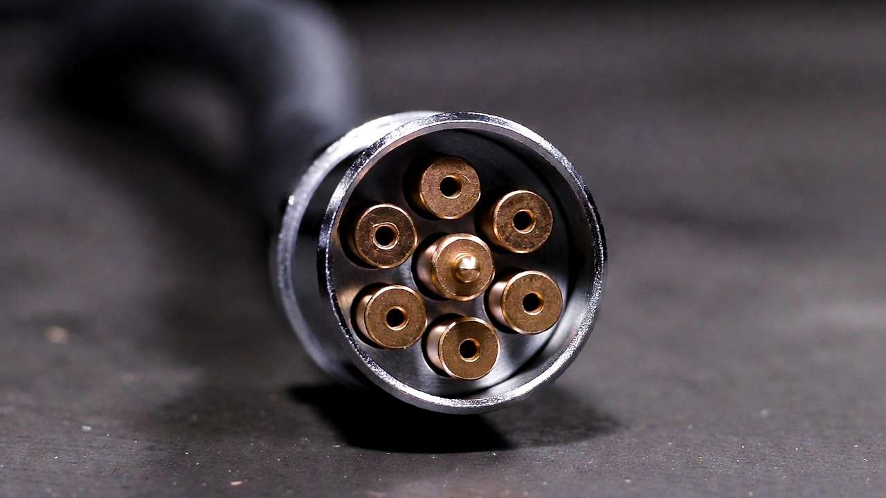
What Is 7 Pin Trailer Wiring and How Does It Work?
At its core, the 7-pin connector (often called a 7-way round plug) is a standardized multi-circuit interface operating on 12V DC systems. It uses seven male pins on the trailer side (plug) that mate with seven female sockets on the vehicle side (receptacle), ensuring positive locking and environmental sealing.
Each pin handles a dedicated function:
- High-current paths (e.g., ground, brake controller output) use heavier gauge wire.
- Low-current signals (e.g., turn indicators) require precise voltage delivery to avoid dimming or failure.
From a mechanical engineering perspective, the system must maintain low resistance (<0.5 ohms typical per circuit) under vibration, temperature swings (-40°C to +85°C), and exposure to road salt, moisture, and debris. Poor contact pressure or corrosion leads to voltage drops, which manifest as flickering lights or weak braking—common real-world failures.
Key Differences Between 7 Pin, 4 Pin, and 5 Pin Systems
Many tow setups start with simpler connectors, but upgrading to 7 pin trailer wiring unlocks essential capabilities for heavier or more complex trailers.
| Connector Type | Pins | Primary Functions | Typical Applications | Limitations |
|---|---|---|---|---|
| 4-Pin Flat | 4 | Ground, Tail/Running lights, Left turn/brake, Right turn/brake | Small utility trailers, boat trailers without brakes | No electric brake control, no auxiliary power, no reverse lights |
| 5-Pin Flat | 5 | Same as 4-pin + one extra (often blue for reverse lights or surge brake lockout) | Trailers with backup lamps or basic hydraulic brakes | Still lacks full electric brake modulation and constant 12V charging |
| 7-Pin Round (SAE J560) | 7 | Ground, Tail lights, Left turn, Right turn, Brake controller output, Auxiliary 12V charge, ABS/constant power | RVs, horse trailers, equipment haulers, commercial trailers | More complex wiring; higher cost but far superior functionality |
The jump to 7-pin becomes necessary when trailers exceed ~3,000 lbs GVWR or include electric-over-hydraulic brakes, interior lights, or battery charging needs. Engineering trade-off: Added complexity improves safety and versatility but demands correct installation to prevent shorts or ground loops.
Historical Evolution and Engineering Importance
Trailer wiring standards trace back to the 1950s with early SAE efforts to standardize lighting for interstate commerce. SAE J560 (first formalized in the 1970s, updated through 2020) became the North American benchmark, driven by FMVSS 108 (lighting) and FMVSS 121 (ABS/brakes) requirements.
Modern 7 pin trailer wiring supports LED lighting (lower current draw), integrated brake controllers, and even smart diagnostics in newer vehicles. In fleet environments I’ve worked in, improper wiring contributes to ~15-20% of roadside breakdowns—highlighting why understanding these systems matters for reliability and compliance.
Standards and Specifications for 7 Pin Trailer Wiring
Compliance with recognized standards ensures interoperability, safety, and longevity.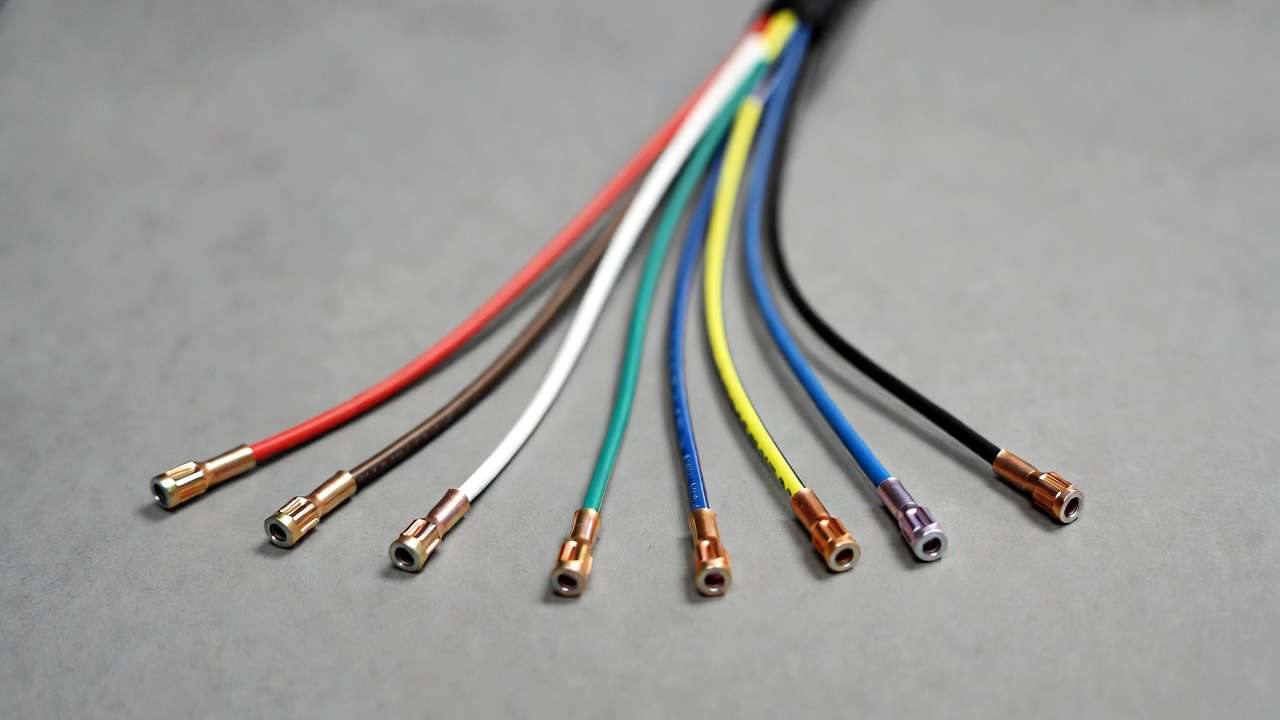
SAE J560 Standard: The North American Benchmark
SAE J560 defines the physical dimensions, electrical ratings, and pin assignments for 7-pin round connectors. Key specs:
- Connector diameter: ~2 inches
- Pin layout: Circular with center ground pin (for best contact reliability)
- Minimum current capacity: 20A on power circuits, 10A+ on lighting
- Environmental: IP67-rated when mated (dust-tight, temporary immersion)
Standard SAE J560 pinout (viewed from male plug end, keyway at top):
| Pin # | Function | Standard Wire Color | Typical Wire Gauge | Notes / Voltage |
|---|---|---|---|---|
| 1 | Ground (White) | White | 8-10 AWG | Common return; must be robust |
| 2 | Clearance/Side Marker/Identification Lamps | Black | 12 AWG | Tail/running lights |
| 3 | Left Turn Signal & Hazard | Yellow | 12-14 AWG | Combined with stop on some |
| 4 | Stop Lamps & ABS (secondary) | Red | 10-12 AWG | Brake lights |
| 5 | Right Turn Signal & Hazard | Green | 12-14 AWG | Combined with stop on some |
| 6 | Tail & License Plate Lamps | Brown | 12-14 AWG | Running lights |
| 7 | Auxiliary Power / ABS Primary / Continuous Power | Blue | 10 AWG | Brake controller + charge line |
(Note: Some configurations swap colors slightly for RV vs. commercial use, but SAE J560 prioritizes white ground and blue auxiliary.)
RV and ISO 11446 Standards: Global Variations
In the U.S., RV manufacturers often follow a “7-way blade” style (different shape but similar functions), while Europe uses ISO 1185/ISO 3731 (7-pin round with reversed ground gender on some). For international towing, adapters are common but introduce failure points—engineers recommend dedicated harnesses.
Wire Gauge, Materials, and Electrical Ratings
Use tinned copper stranded wire for corrosion resistance. Recommended gauges:
- Ground & power: 10 AWG minimum
- Lighting circuits: 14 AWG
- Brake output: 10-12 AWG
Apply Ohm’s law for voltage drop calculations: V_drop = I × R × L × 2 (round trip). Aim for <3% drop under full load to prevent dim lights or weak brakes.
Expert tip: Always fuse the auxiliary (black/blue) circuit at the battery with 30A max to protect against shorts.
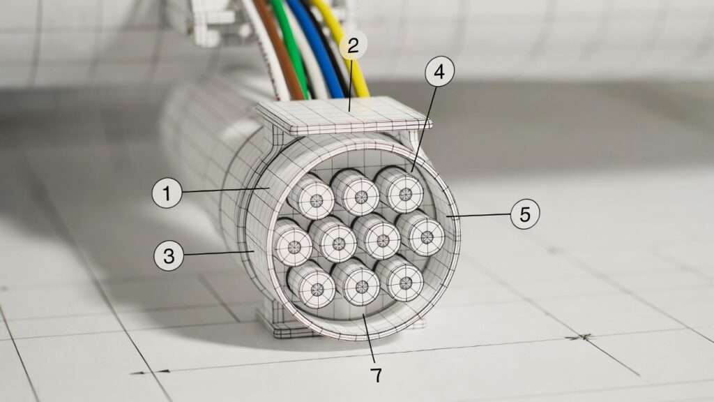
Detailed Wiring Diagrams and Pinouts
Accurate diagrams are the cornerstone of successful 7 pin trailer wiring installation. Misinterpreting a pinout is one of the most frequent causes of crossed signals, non-functional brakes, or blown fuses.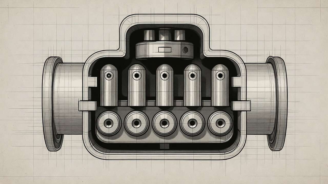
Standard 7 Pin Trailer Wiring Diagram
The classic SAE J560 round 7-pin connector uses a circular arrangement with the large center pin dedicated to ground (white wire). Viewing the male plug (trailer side) face-on with the alignment keyway or flat spot at the top:
- Center: Pin 1 – Ground (White)
- Clockwise from top-right: Pin 2 – Clearance/Markers (Black)
- Next: Pin 3 – Left Turn/Stop (Yellow)
- Bottom: Pin 4 – Stop/Brake Lights (Red)
- Next: Pin 5 – Right Turn/Stop (Green)
- Next: Pin 6 – Tail/License (Brown)
- Top-left: Pin 7 – Auxiliary/Brake Controller (Blue)
In practice, many vehicle-side receptacles are 7-blade (flat rectangular) rather than round, but the function-to-pin mapping remains identical under SAE standards. Always verify your connector type before cutting wires.
For RV-style blade connectors, the layout is typically:
- Top row: Left turn (yellow), Tail (brown), Right turn (green)
- Middle: Ground (white), Brake output (blue)
- Bottom: Reverse/Accessory (often purple or black in some configs), but standard SAE prioritizes blue for brakes/aux.
Expert recommendation: Print and laminate a pinout chart for your toolbox. Label wires with heat-shrink tags during installation to avoid future confusion.
Vehicle-Specific Variations (e.g., Ford, Chevy, Dodge)
Modern trucks often come pre-wired for towing packages:
- Ford Super Duty (2017+): Uses a factory 7-way blade connector behind the bumper; wires are bundled in a harness with color codes matching SAE.
- Chevrolet/GMC Silverado/Sierra: Similar blade style; auxiliary power (blue) is fused at 30A from the under-hood fuse box.
- Ram 1500/2500: Round pin style more common on older models; newer use blade with integrated trailer brake controller port.
If your vehicle lacks a factory harness, you’ll need a universal 7-pin kit. Adapters exist for converting 4-pin or 5-pin factory plugs, but direct wiring is preferred to minimize resistance points.
Custom Configurations for Electric Brakes and Accessories
For trailers with electric-over-hydraulic (EOH) brakes or surge actuators:
- Blue wire connects to the brake controller output (proportional signal).
- Add a dedicated ground for the controller if vehicle ground is noisy.
- For backup cameras or interior lights: Use the auxiliary pin (blue) with a relay or splitter, but never exceed 20A total draw.
Advanced setups (e.g., gooseneck with multiple axles) may require parallel wiring or heavier 8 AWG ground to handle cumulative brake current (up to 30A+ under panic stop).
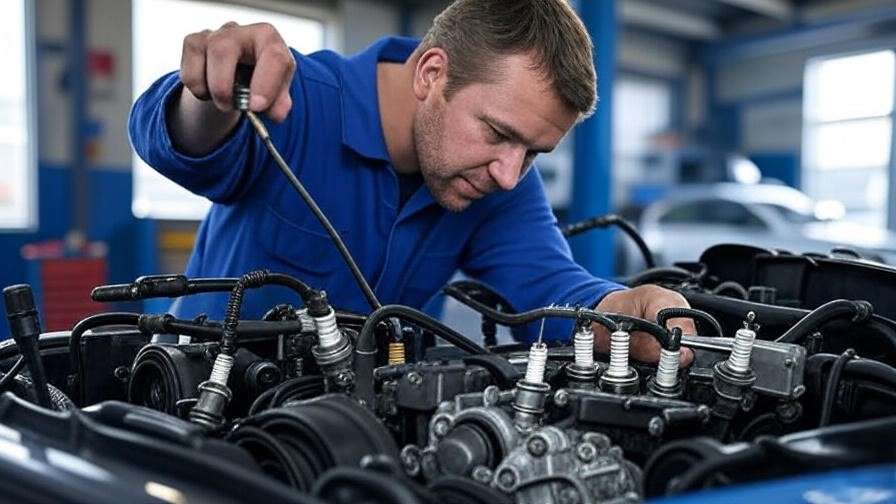
Step-by-Step Installation Guide for 7 Pin Trailer Wiring
Proper installation eliminates 90% of common electrical gremlins. Follow this sequence meticulously.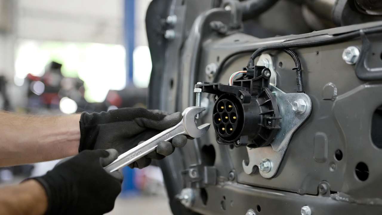
Tools and Materials Required
- 7-pin round or blade connector kit (vehicle + trailer side)
- 10–14 AWG automotive-grade tinned copper wire (color-coded)
- Wire strippers/crimpers, heat gun, dielectric grease
- Multimeter (digital), test light
- Heat-shrink butt connectors, ring terminals, zip ties
- Inline fuse holder (30A for blue wire), 20A for lighting circuits
- Mounting bracket for receptacle, grommets for firewall pass-through
Safety first: Disconnect vehicle battery negative terminal before starting.
Preparing Your Vehicle and Trailer
- Inspect existing wiring for corrosion, fraying, or rodent damage.
- Locate factory tow harness (often near rear bumper or under taillight assembly).
- Clean all ground points with wire brush; apply dielectric grease.
- On trailer: Confirm frame ground is solid (clean to bare metal, <0.2 ohms resistance).
Wiring the Vehicle Side (Plug Installation)
- Route new harness from battery area to rear (use existing grommets or drill carefully).
- Connect white ground to clean chassis point or battery negative (use 10 AWG minimum).
- Tie lighting wires (brown, yellow, green) to corresponding taillight circuits using splice taps or solder.
- Blue wire: Run from brake controller output (or battery via fuse) to connector.
- Black (markers) to running light circuit.
- Secure all connections with heat-shrink; route away from exhaust/heat sources.
- Mount receptacle securely with bracket; seal with silicone if exposed.
Wiring the Trailer Side (Receptacle Installation)
- Match vehicle pinout exactly—reverse polarity can damage modules.
- Connect trailer lights, brakes, and battery charge line per diagram.
- Ground white wire to trailer frame at multiple points for redundancy.
- Test continuity before final mounting.
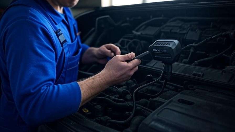
Testing and Verification
- Reconnect battery.
- Use multimeter: Check 12V+ on each pin with corresponding function activated (e.g., brakes depressed → blue pin ~0–12V proportional).
- Verify ground continuity (<0.5 ohms).
- Road test: Confirm all lights, signals, and brake response.
- Load test brakes with trailer attached.
Pro tip from field experience: Always test with a trailer connected—vehicle-side only tests can miss ground loop issues.
Common Issues and Troubleshooting 7 Pin Trailer Wiring
Even with careful installation, problems can arise due to wear, vibration, corrosion, or user error. Here’s a systematic approach to diagnosing and fixing the most frequent issues encountered in real-world towing.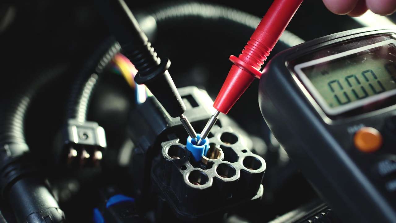
Diagnosing Electrical Faults
Common symptoms and root causes include:
- No lights or intermittent operation Most often a bad ground connection. White wire must have clean, low-resistance contact to chassis on both vehicle and trailer. Test: Measure resistance from white pin to battery negative—should be <0.5 Ω. Fix: Clean ground points, add secondary ground strap if needed.
- Brakes weak or non-functional Blue wire issues: corroded pins, poor crimps, blown fuse, or incompatible brake controller. Check voltage at blue pin while braking (should modulate 0–12V). Also verify trailer brake magnets (resistance ~3–4 Ω per axle). Fix: Replace corroded connectors, use dielectric grease, confirm controller calibration.
- Turn signals or brake lights crossed (left/right swapped) Yellow and green wires reversed. Fix: Swap at connector or splice points.
- Dim or flickering lights Voltage drop from undersized wire, long runs, or corroded splices. Measure voltage at trailer lights with load applied—should be >11.5V. Fix: Upgrade to thicker wire or add relays for high-draw circuits.
- Auxiliary power (battery charging) not working Blown 30A fuse, poor connection at battery, or vehicle-side relay failure. Test: 12V+ constant at blue pin with ignition on. Fix: Check inline fuse, ensure proper routing away from heat.
- ABS light on dash or trailer ABS malfunction Often pin 4 (red) or secondary ground issue in newer systems. Consult vehicle manual for ABS-specific wiring.
Pro troubleshooting sequence:
- Visual inspection for damage/corrosion.
- Continuity test (multimeter beep mode) for each circuit.
- Voltage drop test under load.
- Isolate vehicle vs. trailer by testing with known-good short harness.
Preventive Maintenance Tips
- Apply dielectric grease to all pins every 6 months.
- Inspect harness routing for chafing against frame or exhaust.
- Store trailer disconnected with dust cap on receptacle.
- Use circuit tester plug (7-pin tester tool) before every trip.
- Replace connectors showing green corrosion or pitting immediately.
From fleet maintenance experience: Spending 15 minutes on pre-trip checks prevents 80% of roadside electrical failures.
Safety, Legal, and Advanced Considerations
Towing safety extends far beyond getting lights to work—proper 7 pin trailer wiring is a regulatory and engineering requirement.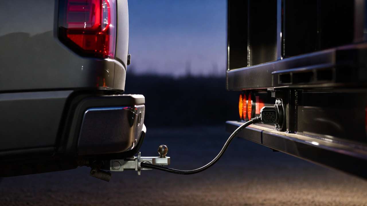
Ensuring Towing Safety and Compliance
- FMVSS 108 mandates functional lighting; non-compliant setups can result in fines or impoundment.
- FMVSS 121 requires working electric brakes on trailers over 3,000 lbs GVWR in many jurisdictions.
- Ground integrity is critical—poor grounds cause unpredictable failures under load.
- Always verify brake performance unloaded first, then loaded on a safe road.
Legal tip: Carry documentation of brake controller certification if operating commercially.
Upgrades and Smart Integrations
- LED Lighting Conversion: Reduces current draw (from 4–5A to <1A per side), allowing thinner wire and less heat.
- Wireless Brake Controllers: Emerging options reduce wiring complexity but require stable 7-pin power.
- EV Towing Adaptations: Many electric trucks use 7-pin but with modified power management—check OEM specs for high-voltage isolation.
- Integrated Diagnostics: Some aftermarket harnesses include CAN-bus interfaces for real-time monitoring via OBD-II.
Future-proof your setup by using modular connectors and leaving service loops in wiring for easy upgrades.
Conclusion – The Unsung Hero of Safe Towing
Mastering 7 pin trailer wiring transforms a potential weak link into a reliable, engineered system that protects you, your cargo, and other road users. By following SAE J560 standards, using proper gauges and materials, installing methodically, and maintaining proactively, you eliminate the majority of common towing electrical headaches.
Whether you’re a weekend DIYer or managing a fleet, the principles here—rooted in mechanical and electrical engineering best practices—deliver consistent results. Take the time to double-check your setup before your next tow. Safe travels, and feel free to share your own wiring experiences or questions in the comments below.
FAQs
- What is the standard color code for 7 pin trailer wiring? White = Ground, Black = Clearance/Markers, Yellow = Left Turn, Red = Stop, Green = Right Turn, Brown = Tail/License, Blue = Auxiliary/Brake Controller.
- Can I use a 4-pin to 7-pin adapter? Yes for basic lighting, but you’ll lose brake control and charging—upgrade to full 7-pin for safety.
- Why does my brake controller show no output? Check blue wire connection, fuse, and ground. Also confirm controller is powered and properly calibrated.
- Is the 7-pin round the same as 7-way blade? Functionally yes (SAE J560), but physical shape differs—use matching plug/receptacle or adapter.
- How do I test 7 pin trailer wiring without a trailer? Use a 7-pin circuit tester or multimeter to verify voltage at each pin with functions activated.
- What gauge wire for 7 pin trailer wiring? 10 AWG for ground, brake, and auxiliary; 12–14 AWG for lighting circuits.
- Why do my trailer lights dim when brakes are applied? Voltage drop—upgrade wire size, clean grounds, or add relays.
- Do I need a breakaway system? Required by law in most states for trailers over 3,000 lbs with electric brakes.
- Can corrosion be prevented on 7-pin connectors? Yes—apply dielectric grease liberally and use weatherproof covers when disconnected.
- What happens if I reverse the ground and power wires? Potential damage to vehicle electronics—always verify polarity with multimeter.