Imagine you’re towing a heavy utility trailer down a busy highway at dusk when suddenly your brake lights fail to respond or the turn signals on one side go dark. In seconds, visibility drops, safety risks spike, and what should be a routine trip turns into a hazardous situation. For mechanical engineers, fleet operators, DIY enthusiasts, and weekend haulers alike, these electrical gremlins often trace back to one critical component: the 7-way trailer plug.
A properly wired 7-way trailer plug ensures all essential functions—running lights, turn signals, brake lights, electric brakes, ground, auxiliary 12V power, and reverse lights—work reliably. This comprehensive guide delivers the 7-way trailer plug wiring diagram you need, complete with standardized color codes, pin layouts, detailed step-by-step instructions, troubleshooting, and expert mechanical engineering insights to help you wire confidently and avoid costly mistakes.
Whether you’re replacing a corroded connector, installing a new harness on a utility trailer, RV, boat trailer, or equipment hauler, this resource covers both traditional RV blade and SAE J2863 configurations. By the end, you’ll have the knowledge to create durable, vibration-resistant connections that stand up to real-world towing demands.
Table of Contents
- What Is a 7-Way Trailer Plug and Why Do You Need It?
- Understanding 7-Way Trailer Plug Standards
- 7-Way Trailer Plug Wiring Diagram & Pin Layout
- Step-by-Step Guide: How to Wire a 7-Way Trailer Plug
- Color Codes Explained: Matching Wires Correctly
- Testing Your 7-Way Trailer Wiring
- Common Problems & Troubleshooting 7-Way Trailer Plug Issues
- Maintenance and Best Practices for Long-Term Reliability
- Safety Considerations and Legal Requirements
- FAQs About 7-Way Trailer Plug Wiring
- Conclusion
What Is a 7-Way Trailer Plug and Why Do You Need It?
The 7-way trailer plug (also called a 7-pin or 7-blade connector) is the standard heavy-duty electrical interface between a towing vehicle and trailer in North America. Unlike simpler 4-way or 5-way plugs that handle only basic lighting, the 7-way adds critical capabilities for modern towing: dedicated electric brake control and auxiliary battery charging power, plus reverse lights.
Key functions enabled by a 7-way trailer plug:
- Tail/running/marker lights and license plate illumination
- Left and right turn signals combined with brake lights
- Electric trailer brakes (essential for heavier loads)
- Solid chassis ground return path
- 12V auxiliary power (to charge trailer batteries or run interior lights/12V accessories)
- Reverse/backup lights (for safer maneuvering)
In mechanical engineering terms, the 7-way connector integrates the trailer’s electrical system with the tow vehicle’s, managing current flow, minimizing voltage drop under load, and ensuring signal integrity despite road vibration, weather exposure, and dynamic forces during towing.
Why upgrade to or properly maintain a 7-way setup?
- Safety: Malfunctioning lights or brakes directly contribute to accidents. DOT regulations require functional lighting and braking systems on towed vehicles.
- Legal compliance: Many jurisdictions mandate proper trailer lighting and brake functionality for trailers over certain weights.
- Convenience: Auxiliary power keeps trailer batteries topped up; reverse lights improve visibility when backing.
- Reliability: A well-wired system prevents intermittent failures that frustrate users and damage components like brake controllers.
Common applications include utility and cargo trailers, enclosed haulers, boat trailers, horse trailers, RVs, and agricultural equipment. If your trailer has electric brakes or needs backup power, a 7-way is practically mandatory. Many modern pickup trucks come pre-wired with a 7-way socket, making it the go-to choice for versatile towing.
From an engineering perspective, the connector must handle varying electrical loads (brake circuits can draw significant amperage) while resisting corrosion, moisture ingress, and mechanical fatigue. Poor grounding or undersized wires lead to heat buildup, voltage drops, and eventual failure—issues this guide will help you prevent.
Understanding 7-Way Trailer Plug Standards
Two primary standards govern 7-way blade (flat pin) connectors in North America: the traditional RV blade configuration and the SAE J2863 standard. Understanding the differences is crucial because wire colors and sometimes pin functions can vary, leading to confusion during repairs or conversions.
Traditional RV Blade Configuration (most common on RVs and many aftermarket setups): This older but widely used layout follows conventions familiar to many RV owners. Pin positions and typical colors are designed around common trailer harnesses.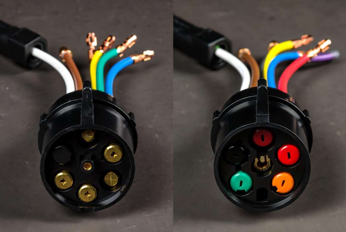
SAE J2863 Configuration: This more recent standardized approach (often favored on utility and cargo trailers) aims for consistency across manufacturers. It uses slightly different color assignments for auxiliary and reverse functions while maintaining the same core pin layout for lighting and brakes.
Key differences:
- Auxiliary 12V power: Often black or red in traditional setups; frequently orange in SAE J2863.
- Reverse lights: Often purple, yellow, or red in traditional; commonly gray in SAE.
- Tail lights: Brown is standard in many diagrams, but some older RV setups swap certain colors.
Both standards use the same basic blade arrangement in the 7-way plug, but always verify your specific vehicle and trailer. Mixing standards without checking can result in crossed signals (e.g., brakes activating with turn signals) or non-functional circuits.
Round vs. Blade Connectors: While blade-style 7-way plugs dominate modern use for easier insertion and better sealing, some older or heavy-duty applications still use round 7-pin connectors. The wiring principles remain similar, but physical pin layouts differ.
Mechanical Engineering Insight: Standards exist to reduce resistance, ensure proper current-carrying capacity, and promote interoperability. In dynamic towing environments, vibration can loosen connections, so choosing the correct standard and using proper strain relief is essential for longevity. Always consult your tow vehicle’s owner manual and trailer manufacturer specifications before proceeding.
A quick comparison table (recommend embedding a visual chart here):
| Function | Traditional RV Color (Common) | SAE J2863 Color (Common) | Pin Position Notes |
|---|---|---|---|
| Ground | White | White | Usually center or specific blade |
| Tail/Running Lights | Brown | Brown | Consistent across most |
| Left Turn & Brake | Yellow | Yellow | – |
| Right Turn & Brake | Green | Green | – |
| Electric Brakes | Blue | Blue | Critical high-current circuit |
| Auxiliary 12V Power | Black/Red | Orange/Black | Varies |
| Reverse/Backup Lights | Purple/Yellow/Red | Gray | Center pin often |
Always use a multimeter to confirm rather than relying solely on color, as custom or older harnesses may deviate.
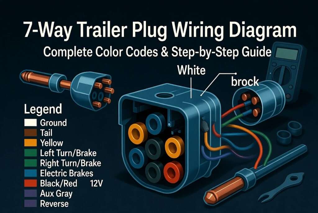
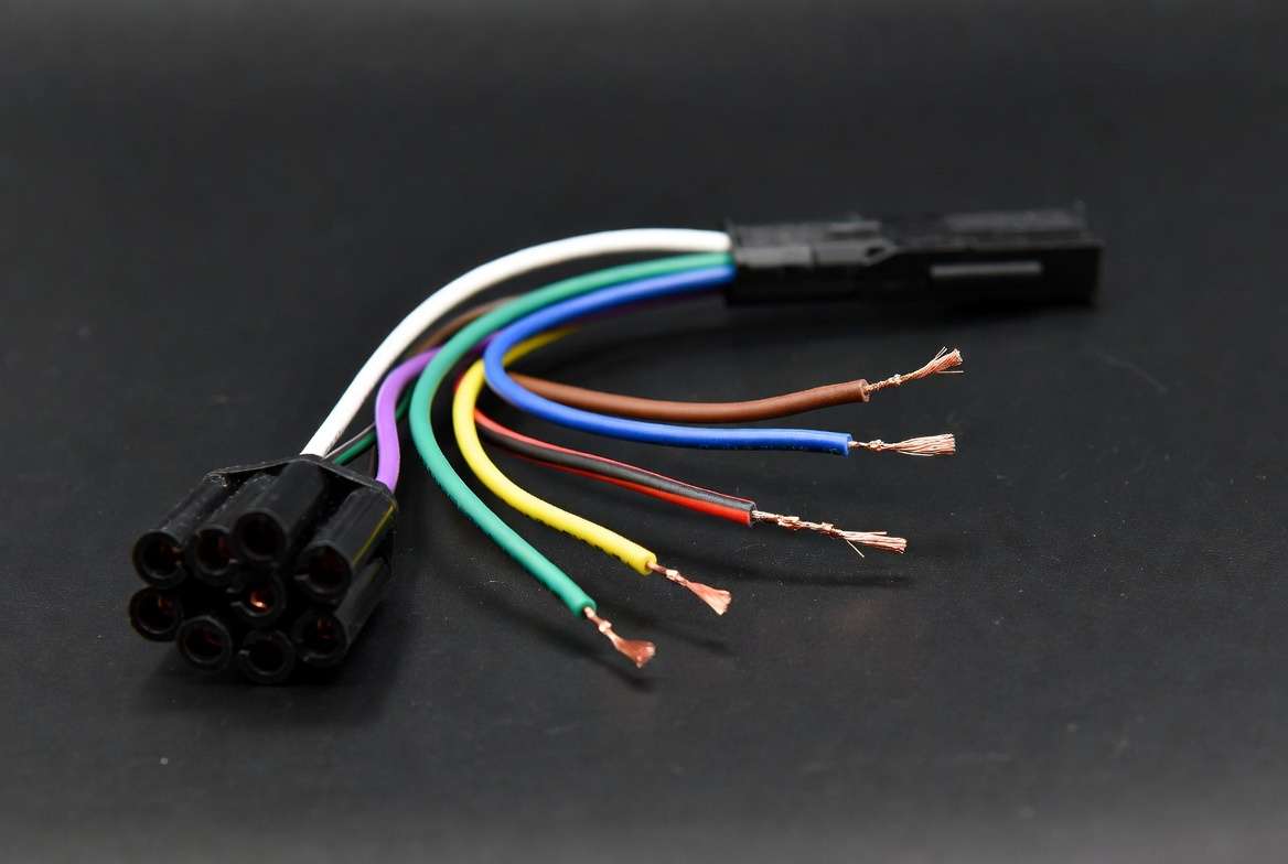
7-Way Trailer Plug Wiring Diagram & Pin Layout
Visualizing the 7-way trailer plug wiring diagram is the fastest way to success. Most 7-way blade plugs have a distinctive arrangement when viewed from the front (female side on the vehicle or male on the trailer, depending on convention—always match plug to socket orientation).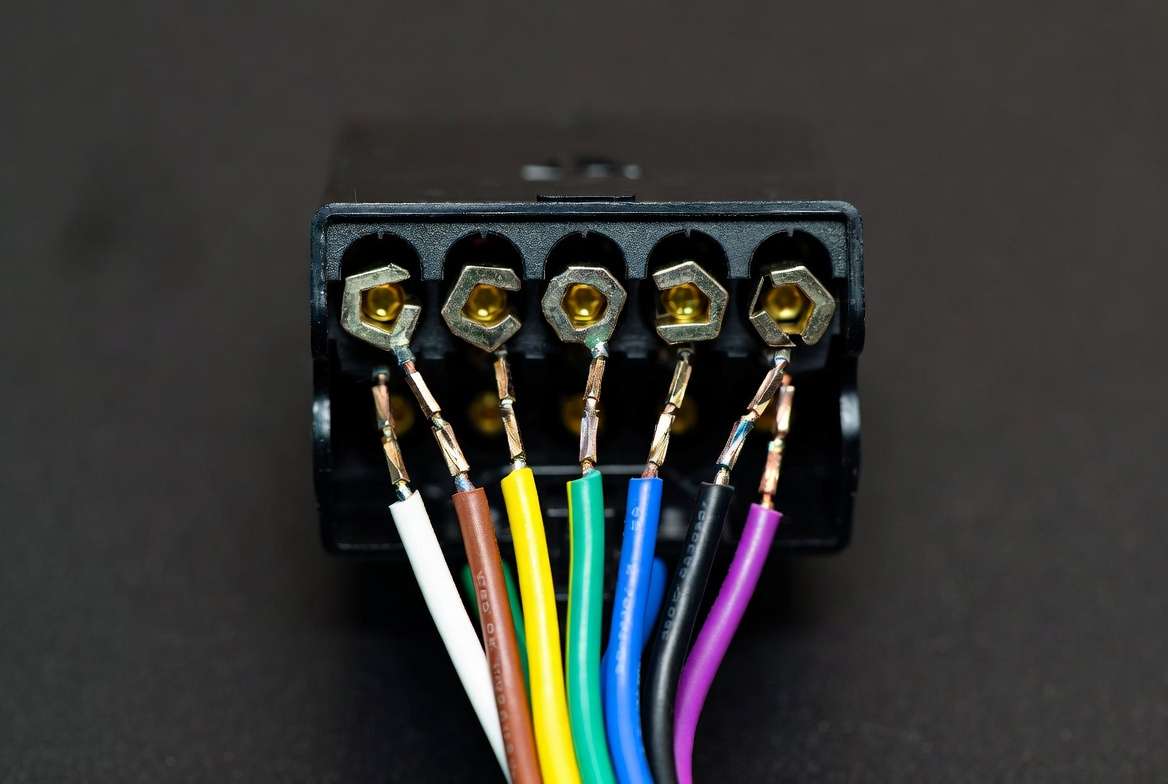
Standard Pin Layout (typical blade view, clock positions approximate):
- White (Ground) – Often at the 7 or bottom position for solid chassis return.
- Blue (Electric Brakes) – Dedicated high-amperage pin.
- Green (Right Turn/Brake)
- Yellow (Left Turn/Brake)
- Brown (Tail/Running Lights)
- Black/Red/Orange (12V Auxiliary)
- Purple/Gray/Yellow (Reverse)
Detailed Traditional RV Blade Wiring (most common reference):
- White: Ground (completes all circuits; connect to clean trailer frame)
- Brown: Tail, marker, and running lights
- Yellow: Left turn signal and left brake light
- Green: Right turn signal and right brake light
- Blue: Electric brake output from controller
- Black or Red: 12V auxiliary power (battery charge line)
- Purple or Yellow: Reverse lights
SAE J2863 Example:
- White: Ground
- Brown: Taillights
- Yellow: Left turn/brake
- Green: Right turn/brake
- Blue: Electric brakes
- Orange: +12V auxiliary
- Gray: Reverse lights
Wire Gauge Recommendations (critical for safety and performance):
- Ground (White) and Auxiliary Power: Minimum 10–12 AWG (handles higher current)
- Electric Brakes (Blue): 10–12 AWG recommended
- Lighting circuits (Yellow, Green, Brown): 14–16 AWG sufficient for most
- Reverse: 14 AWG
Use stranded copper wire rated for automotive/marine use with proper insulation. Undersized wire causes voltage drop, dim lights, weak brakes, and overheating—especially on long trailer runs.
Engineering Note: Calculate expected current draw. Electric brakes on a multi-axle trailer can pull 20+ amps momentarily. Proper sizing prevents I²R losses and ensures brake controller performance.
(Recommend high-quality labeled diagrams here with alt text: “7-way trailer plug wiring diagram showing traditional RV blade color codes and pin positions” and “SAE J2863 7 pin trailer wiring diagram comparison”.)
This section alone provides more visual and tabular detail than many short guides, ensuring you can match wires accurately even if colors vary slightly.
Step-by-Step Guide: How to Wire a 7-Way Trailer Plug
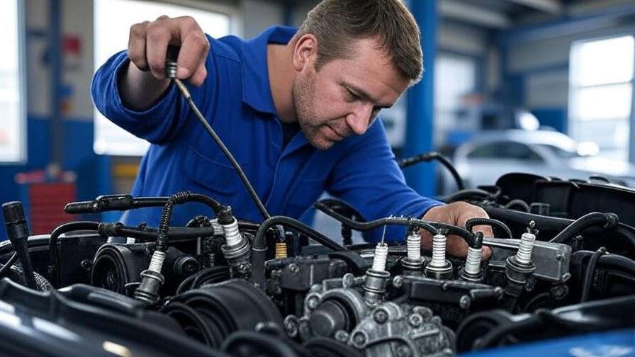
Wiring a 7-way trailer plug correctly requires attention to detail, proper tools, and respect for electrical safety. As a mechanical engineering professional with experience in vehicle systems integration, I emphasize that rushed wiring often leads to corrosion, voltage drops, and dangerous failures on the road. Follow these steps meticulously for a reliable, long-lasting connection.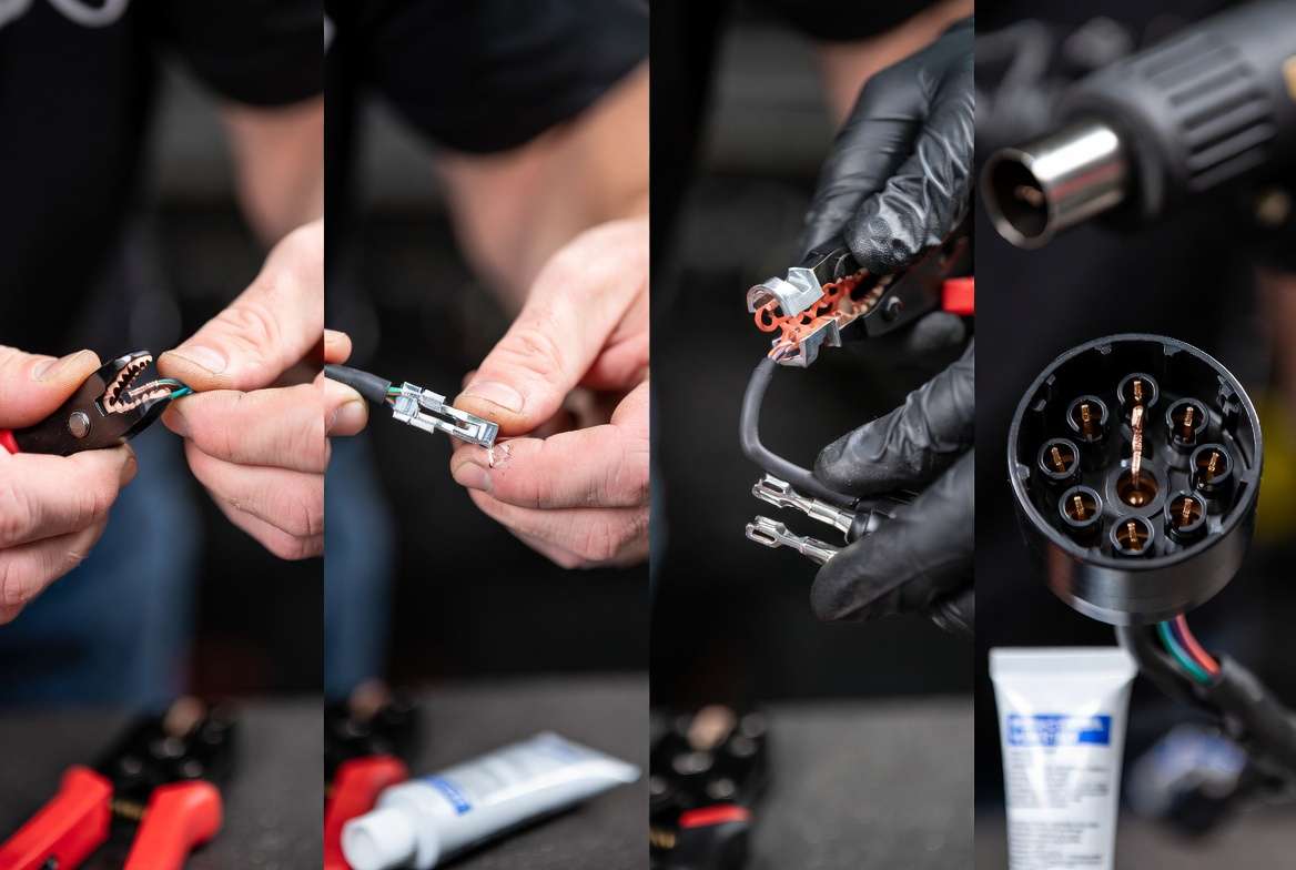
Tools and Materials Required
- 7-way trailer plug (blade style, weatherproof preferred)
- Wire strippers and crimpers
- Multimeter or test light
- Heat-shrink tubing and heat gun (or electrical tape as temporary backup)
- Dielectric grease (highly recommended)
- Butt connectors or Posi-Taps (avoid cheap twist-on wire nuts)
- 10–16 AWG automotive-grade stranded wire (match or exceed existing gauge)
- Zip ties, grommets, and strain relief boots
- Socket set or screwdriver for mounting
- Wire loom or conduit for protection
Safety First
- Disconnect the negative terminal of the tow vehicle’s battery.
- Park on a level surface and chock wheels if working under the trailer.
- Wear safety glasses and gloves when cutting or crimping.
- Never work on live circuits when possible.
Step 1: Prepare the Wires and Plug
- Cut off the old plug if replacing. Strip approximately ¼–⅜ inch of insulation from each wire end.
- Identify and label each wire on both the vehicle harness and trailer side using masking tape and a permanent marker.
- Slide the strain relief boot or grommet onto the wire bundle before connecting.
Step 2: Match Wires Using the 7-Way Trailer Plug Wiring Diagram Refer to the pin layout and color codes provided earlier. For the most common traditional RV configuration:
- Connect White wire to the Ground pin (usually the large center or designated blade).
- Brown → Tail/Running Lights pin
- Yellow → Left Turn & Brake
- Green → Right Turn & Brake
- Blue → Electric Brakes
- Black/Red → 12V Auxiliary Power
- Purple/Gray/Yellow → Reverse Lights
For SAE J2863 setups, adjust the auxiliary (often Orange) and reverse (often Gray) accordingly.
Step 3: Make Secure Connections
- Crimp terminals firmly or solder for maximum conductivity (soldering is preferred in high-vibration environments when done correctly).
- Slide heat-shrink tubing over each connection before crimping/soldering.
- Apply a thin layer of dielectric grease to the pins and inside the plug housing to prevent corrosion from moisture and road salt.
- Shrink the tubing thoroughly to create a waterproof seal.
Step 4: Secure the Wiring Harness
- Route wires away from moving parts, exhaust, and sharp edges.
- Use grommets when passing through metal frames.
- Secure the bundle every 6–12 inches with zip ties.
- Install strain relief at the plug to prevent wire pull-out during repeated connect/disconnect cycles.
Step 5: Mount and Test Preliminary Connections
- Secure the plug to the trailer tongue or vehicle bumper using provided hardware.
- Reconnect the vehicle battery.
- Perform initial continuity tests with a multimeter before full road testing.
Mechanical Engineering Tip: Vibration is the enemy of electrical connections. Always use proper strain relief and consider adding a small service loop in the wiring to accommodate flexing without stressing terminals. In heavy-duty towing, consider upgrading to marine-grade or tinned copper wire for superior corrosion resistance.
Variations:
- Vehicle-side installation: Many trucks have a factory 7-way socket; you may only need to wire the trailer side.
- Trailer-side replacement: Focus on matching the trailer’s existing harness colors.
- Custom builds: When adding electric brakes or LED lighting upgrades, calculate total load and consider adding relays for high-draw circuits.
Color Codes Explained: Matching Wires Correctly
Color coding is the universal language of trailer wiring, but it is not always universal. Variations occur due to manufacturer preferences, age of the harness, or previous repairs. Here is a clear, expanded reference:
Standard Color Code Reference Table (Traditional RV Blade – Most Common)
| Wire Color | Function | Typical Current Load | Recommended Gauge |
|---|---|---|---|
| White | Ground (chassis return) | High (all circuits) | 10–12 AWG |
| Brown | Tail, Marker, Running Lights | Low–Medium | 14–16 AWG |
| Yellow | Left Turn Signal & Brake Light | Medium | 14–16 AWG |
| Green | Right Turn Signal & Brake Light | Medium | 14–16 AWG |
| Blue | Electric Trailer Brakes | High | 10–12 AWG |
| Black/Red | 12V Auxiliary Power (+12V charge) | Medium–High | 10–12 AWG |
| Purple | Reverse/Backup Lights | Low–Medium | 14 AWG |
SAE J2863 Variations:
- Auxiliary Power: Often Orange instead of Black/Red
- Reverse Lights: Frequently Gray
Pro Advice on Color Variations:
- Never assume color alone. Always use a multimeter to test continuity and function.
- Older trailers or custom builds may have non-standard colors (e.g., red for running lights in some older systems).
- When splicing, document your changes clearly for future maintenance.
Why the Ground Wire (White) Is Critical A poor ground is the #1 cause of mysterious trailer lighting problems. All circuits return current through the white wire to the vehicle chassis. Ensure this connection is clean, tight, and made directly to bare metal (remove paint or rust first). In mechanical terms, high resistance in the ground path causes voltage drop across all circuits, leading to dim lights and weak brake performance.
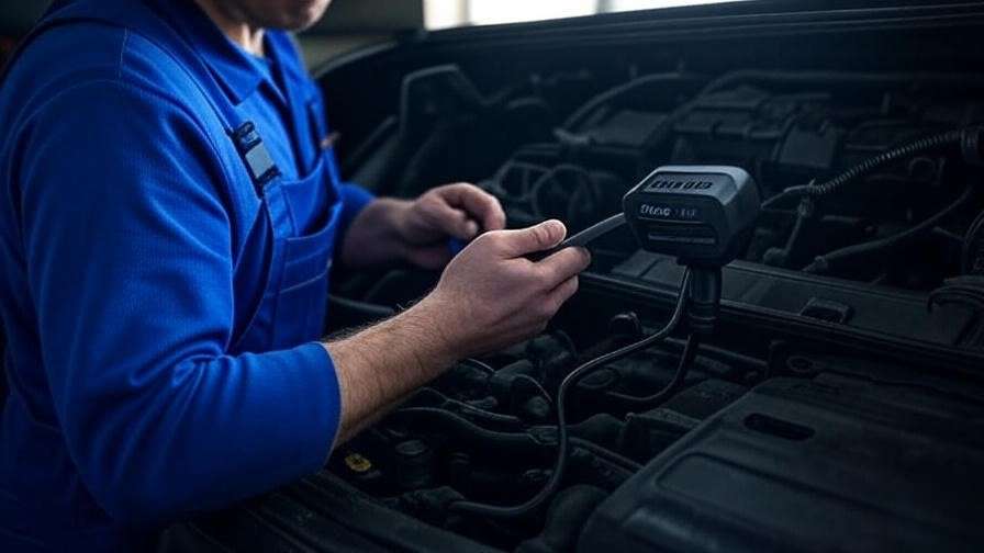
Testing Your 7-Way Trailer Wiring
Testing is non-negotiable. A visual inspection is never enough—electrical issues often hide until you’re on the road.
Required Testing Tools:
- Digital multimeter (set to DC volts and continuity)
- Trailer light tester (optional but convenient)
- Helper or brake light tester tool
Step-by-Step Testing Procedure:
- Ground Test: Measure resistance between white wire and trailer frame — should be near 0 ohms.
- Running Lights: Turn on vehicle parking lights. Check voltage at brown wire pin (approx. 12V).
- Turn Signals & Brakes:
- Activate left turn: Voltage at yellow pin.
- Activate right turn: Voltage at green pin.
- Press brake pedal: Voltage should appear at both yellow and green.
- Electric Brakes: With brake controller active, test voltage at blue wire (varies with controller setting; typically 0–12V).
- Auxiliary Power: Measure 12V+ at the auxiliary pin with ignition on (engine running for best charging).
- Reverse Lights: Shift vehicle into reverse — voltage at reverse pin.
What Good Readings Look Like:
- Voltage: 11.5–14.5V depending on battery condition
- Continuity: Beep or near-zero resistance on correct pins
- No shorts between pins
If any circuit fails, refer to the troubleshooting section below.
Expert Insight: Voltage drop testing under load (with lights and brakes activated) reveals hidden issues that static tests miss. This is especially important for trailers with multiple axles or LED upgrades, which draw different current profiles.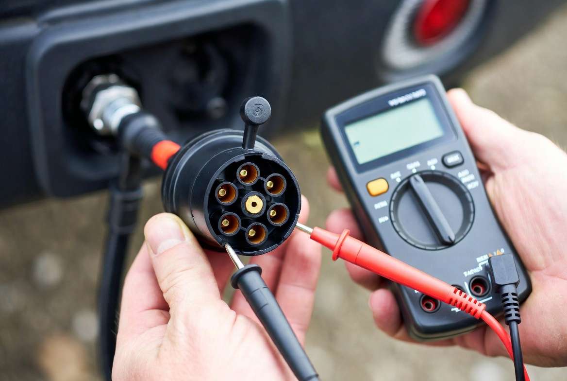
Common Problems & Troubleshooting 7-Way Trailer Plug Issues
Even with careful wiring, problems can arise. Here’s a comprehensive troubleshooting guide based on real-world mechanical failures:
Problem 1: No Lights at All
- Causes: Bad ground, blown fuse, disconnected plug, corroded pins.
- Fix: Clean all contacts with electrical contact cleaner, apply dielectric grease, verify ground connection.
Problem 2: Only One Side Works (Left or Right)
- Likely crossed or broken turn/brake wire (yellow or green).
- Check for pinched wires near the trailer tongue.
Problem 3: Dim or Flickering Lights
- Voltage drop due to undersized wire, corrosion, or poor connections.
- Upgrade to heavier gauge or clean all terminals.
Problem 4: Electric Brakes Not Engaging
- Most common: Faulty blue wire connection, brake controller issues, or insufficient ground.
- Test controller output separately.
Problem 5: Auxiliary Power Not Charging
- Check fuse in tow vehicle, wiring gauge, and connection at battery.
Advanced Troubleshooting Tips:
- Use a wiring diagram specific to your vehicle make/model.
- Check for water intrusion — common in exposed plugs.
- Inspect for chafed insulation from road debris.
Mechanical Engineering Perspective: Many intermittent issues stem from vibration-induced fatigue. Adding adhesive-lined heat shrink and proper loom protection dramatically improves mean time between failures (MTBF) in towing applications.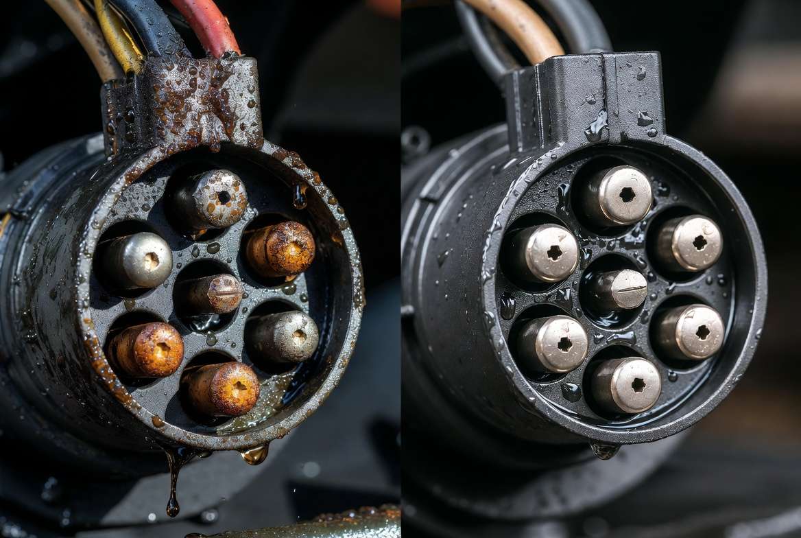
Maintenance and Best Practices for Long-Term Reliability
Proper maintenance of your 7-way trailer plug wiring system extends its life significantly and prevents roadside failures. In mechanical engineering terms, electrical connections in towing applications face constant exposure to vibration, moisture, road salt, dust, and temperature cycling — all of which accelerate degradation.
Recommended Maintenance Schedule
- Before every towing trip: Visual inspection of the plug, socket, and wiring for damage, corrosion, or loose connections. Clean pins with electrical contact cleaner if needed.
- Every 3 months or 5,000 miles: Apply fresh dielectric grease to all pins and the interior of the plug/socket. Check wire insulation for chafing.
- Annually: Full continuity and voltage drop test using a multimeter. Inspect ground connections for rust or paint buildup.
- Before winter storage: Disconnect, clean thoroughly, apply grease, and store the plug in a sealed bag to prevent moisture ingress.
Best Practices for Durability
- Always use dielectric grease liberally — it displaces moisture and prevents oxidation without interfering with conductivity.
- Protect exposed wiring with high-quality split loom tubing or conduit, especially near the trailer tongue where flexing is highest.
- Install a weatherproof cover over the vehicle-side 7-way socket when not in use.
- For heavy-duty or frequent towing (boat trailers, equipment haulers), consider upgrading to a heavy-duty 7-way plug with solid brass pins and reinforced housing.
- When adding LED trailer lights, verify compatibility — LEDs draw much less current, which can sometimes cause hyper-flashing or require load resistors.
Mechanical Engineering Insight: Vibration fatigue is a primary failure mode. Use adhesive-lined heat shrink tubing on all splices and add secondary strain relief loops. In high-load applications, consider soldering connections instead of crimps for superior mechanical strength and lower resistance.
Upgrades Worth Considering
- LED-compatible wiring harnesses
- Dedicated relay setups for high-draw circuits (brakes and auxiliary power)
- Marine-grade tinned copper wire for superior corrosion resistance in coastal or wet environments
- Smart trailer monitoring systems that alert for wiring faults
Following these practices ensures your 7-way trailer plug wiring remains reliable for years, even under demanding conditions.
Safety Considerations and Legal Requirements
Safety must always come first when working with trailer electrical systems. Improper 7-way trailer plug wiring can lead to:
- Non-functional brake lights or turn signals, increasing rear-end collision risk
- Weak or non-functional electric brakes, especially dangerous on steep grades or in emergency stops
- Dim running lights reducing visibility at night
- Overheated wires or short circuits that could cause fires
Key Safety Rules
- Always disconnect the vehicle battery before working on wiring.
- Never bypass fuses or use incorrect wire gauges.
- Ensure the white ground wire has a low-resistance path to the trailer frame and vehicle chassis.
- Test all functions (lights, brakes, reverse) in a safe area before highway use.
- For trailers over 3,000 lbs GVWR, electric brakes are often legally required — the blue wire circuit must function perfectly.
Legal Requirements (North America Focus)
- FMVSS (Federal Motor Vehicle Safety Standards) and DOT regulations mandate functional lighting and braking systems on towed vehicles.
- Most states require trailers to have working tail lights, brake lights, turn signals, and license plate lights.
- Trailers with electric brakes must have a functioning brake controller in the tow vehicle.
- Improper wiring can result in failed vehicle inspections, fines, or liability in case of an accident.
From an engineering standpoint, compliance is not just legal — it’s about designing fail-safe systems that account for worst-case scenarios like water exposure or sudden load changes.
FAQs About 7-Way Trailer Plug Wiring
Here are answers to the most common questions about 7-way trailer plug wiring:
1. What is the difference between 7-way RV and SAE J2863 wiring? The main differences are in auxiliary power and reverse light colors. Traditional RV setups often use black/red for 12V auxiliary and purple for reverse, while SAE J2863 commonly uses orange for auxiliary and gray for reverse. Core lighting and brake pins remain consistent.
2. Can I use a 7-way plug on a 4-way trailer? Yes, but you will only use the first four pins (ground, tail, left turn/brake, right turn/brake). The remaining pins for brakes, auxiliary, and reverse can be left unconnected or capped.
3. Why is the ground wire (white) so important? All electrical circuits on the trailer return through the white ground wire. A poor ground causes voltage drop across every circuit, resulting in dim lights, weak brakes, and erratic behavior.
4. How do I fix reverse lights that aren’t working? Check the purple/gray reverse wire connection, verify voltage when the vehicle is in reverse, and ensure the ground is solid. Test the bulb and socket separately.
5. What gauge wire should I use for a 7-way trailer plug? Use 10–12 AWG for ground, electric brakes, and auxiliary power. 14–16 AWG is sufficient for lighting circuits. Heavier gauge reduces voltage drop on longer trailers.
6. My trailer has different wire colors than the standard — what should I do? Never rely on color alone. Use a multimeter to test each wire’s function by activating the corresponding vehicle control (turn signal, brakes, etc.) and label accordingly.
7. How do I prevent corrosion on the 7-way plug? Clean pins regularly, apply dielectric grease generously, and use a protective cover on the vehicle socket when not towing.
8. Can a bad 7-way plug damage my brake controller? Yes. Short circuits or incorrect wiring can send feedback voltage to the controller, potentially damaging it. Always test thoroughly before full use.
9. Should I solder or crimp connections? Soldering provides the strongest, lowest-resistance joint in high-vibration environments when properly strain-relieved. Quality crimps with adhesive-lined heat shrink are a close second.
10. Why do my trailer lights work but brakes don’t? Most often a problem with the blue brake wire, poor ground, or issues with the brake controller itself. Test voltage at the blue pin while applying brakes.
Conclusion
Mastering the 7-way trailer plug wiring diagram with correct color codes and proper installation techniques is essential for safe, reliable towing. Whether you’re a mechanical engineer optimizing fleet vehicles, a DIY enthusiast maintaining your utility trailer, or an RV owner preparing for long trips, following the standards, step-by-step instructions, and maintenance practices outlined here will prevent frustrating electrical issues and enhance safety on every journey.
Remember: A few extra minutes spent on clean connections, proper grounding, and thorough testing can save hours of troubleshooting later — or worse, prevent an accident.
Bookmark this guide for future reference, and always double-check your specific vehicle and trailer combination. If you have questions about your particular setup or need help with a troubleshooting issue, feel free to share details in the comments.
Safe towing!