Imagine flipping a light switch in a dimly lit workshop or control room, only to have it fail—leaving you fumbling in the dark or, worse, dealing with a potential electrical hazard. For mechanical engineers, DIY homeowners, or anyone integrating electrical systems into mechanical designs—like HVAC controls, prototype enclosures, or facility lighting—understanding light switch wiring diagrams is essential. A single miswired connection can cause flickering lights, intermittent failures, safety risks such as shocks or fires, or even non-compliance with building codes.
This comprehensive guide demystifies light switch wiring diagrams, providing clear, expert-level explanations, detailed diagrams (to be embedded in the final article), step-by-step instructions, and engineering insights. Whether you’re replacing a faulty switch in a home setup or designing reliable electromechanical systems, mastering these basics ensures safe, efficient installations. We’ll cover everything from fundamental concepts to advanced multi-location controls, troubleshooting, and code compliance—going beyond basic tutorials to deliver skyscraper-level depth and value.
Understanding the Basics of Light Switch Wiring
Before diving into diagrams and installations, grasp the core principles. Light switch wiring follows fundamental electrical circuit rules: power flows from the source (breaker panel) through the switch to the load (light fixture) and returns via neutral, with grounding for safety.
Key Electrical Terms and Concepts
- Voltage: In residential systems (US/Canada), typically 120V AC.
- Current: Measured in amps; lighting circuits usually use 15A or 20A breakers.
- Hot wire: Carries live current from the panel (usually black or red).
- Neutral wire: Completes the circuit back to the panel (usually white).
- Ground wire: Provides a safe path for fault current (green or bare copper).
- Switch types:
- Single-pole: Controls one light from one location (most common).
- 3-way: Controls one light from two locations (e.g., hallway ends).
- 4-way: Adds control from three or more locations.
- Dimmer/smart switches: Often require neutrals for modern electronics.
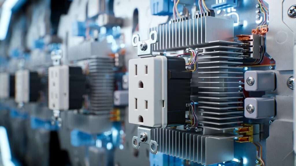
In mechanical engineering contexts, these switches often integrate into larger systems, such as control panels where reliable switching prevents downtime in machinery or automated lighting in prototypes.
Wire Color Codes and Standards (NEC 2023+ Updates)
Per the National Electrical Code (NEC), standardized colors prevent errors:
- Black or red: Hot (line voltage).
- White or gray: Neutral (must be used as neutral unless re-identified).
- Green or bare copper: Ground.
- In switch loops (power to fixture first), white wires may carry hot current but must be marked with black/red tape.
The 2023 NEC emphasizes safety for lighting controls: Wall-mounted devices (including switches) cannot rely solely on battery power without backup to energize outlets if the battery fails (Section 210.70). This impacts smart switches, ensuring reliability in critical applications.
Always consult local codes, as some jurisdictions adopt amendments.
Tools and Materials Needed
For safe, professional work:
- Non-contact voltage tester (essential for verifying power off).
- Multimeter for continuity checks.
- Wire strippers, needle-nose pliers, screwdrivers (flat/Phillips).
- Wire nuts (assorted sizes), electrical tape.
- Insulated gloves, safety glasses.
- Cable staples or clamps for securing wires.
- New switch (rated for load, e.g., 15A for standard lighting).
For engineers: Consider load calculations if integrating multiple fixtures or longer runs to avoid voltage drop.
Common Types of Light Switch Wiring Diagrams
Light switch wiring varies by configuration. Below are the most practical setups, with textual descriptions of standard diagrams (embed annotated images in the published article for visual clarity).
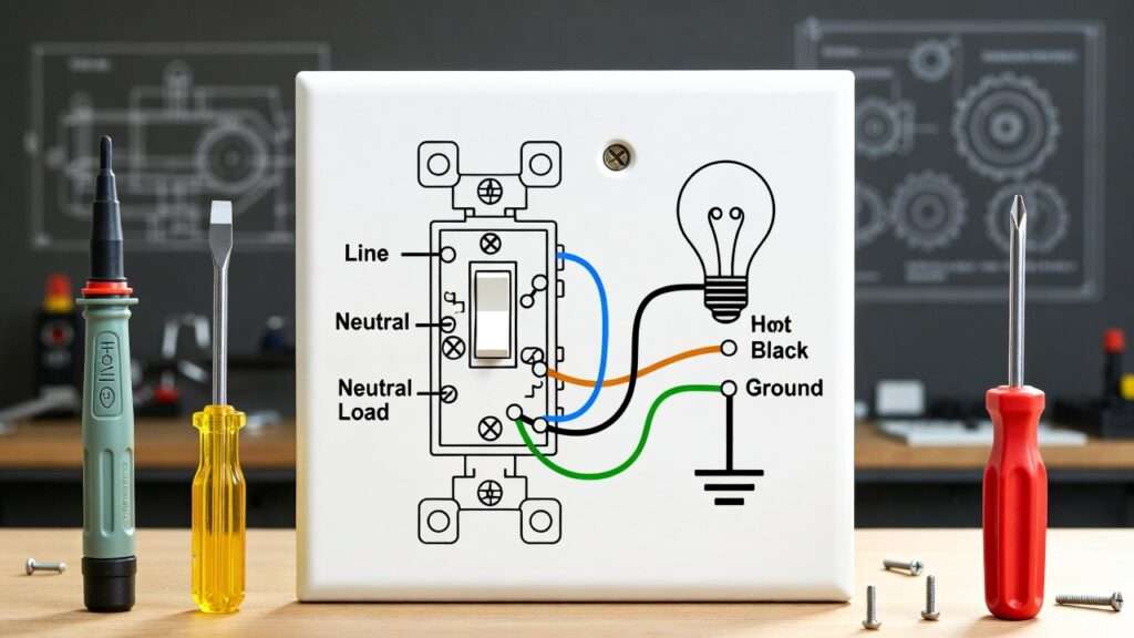
Single-Pole Light Switch Wiring Diagram (Most Common)
This controls one light from one switch.
Power to switch first (preferred for easier troubleshooting):
- Incoming hot (black) to switch’s brass screw.
- Switched hot (black) from switch’s other brass screw to light fixture.
- Neutrals (white) connect directly from source to fixture.
- Grounds connect together and to switch ground screw.
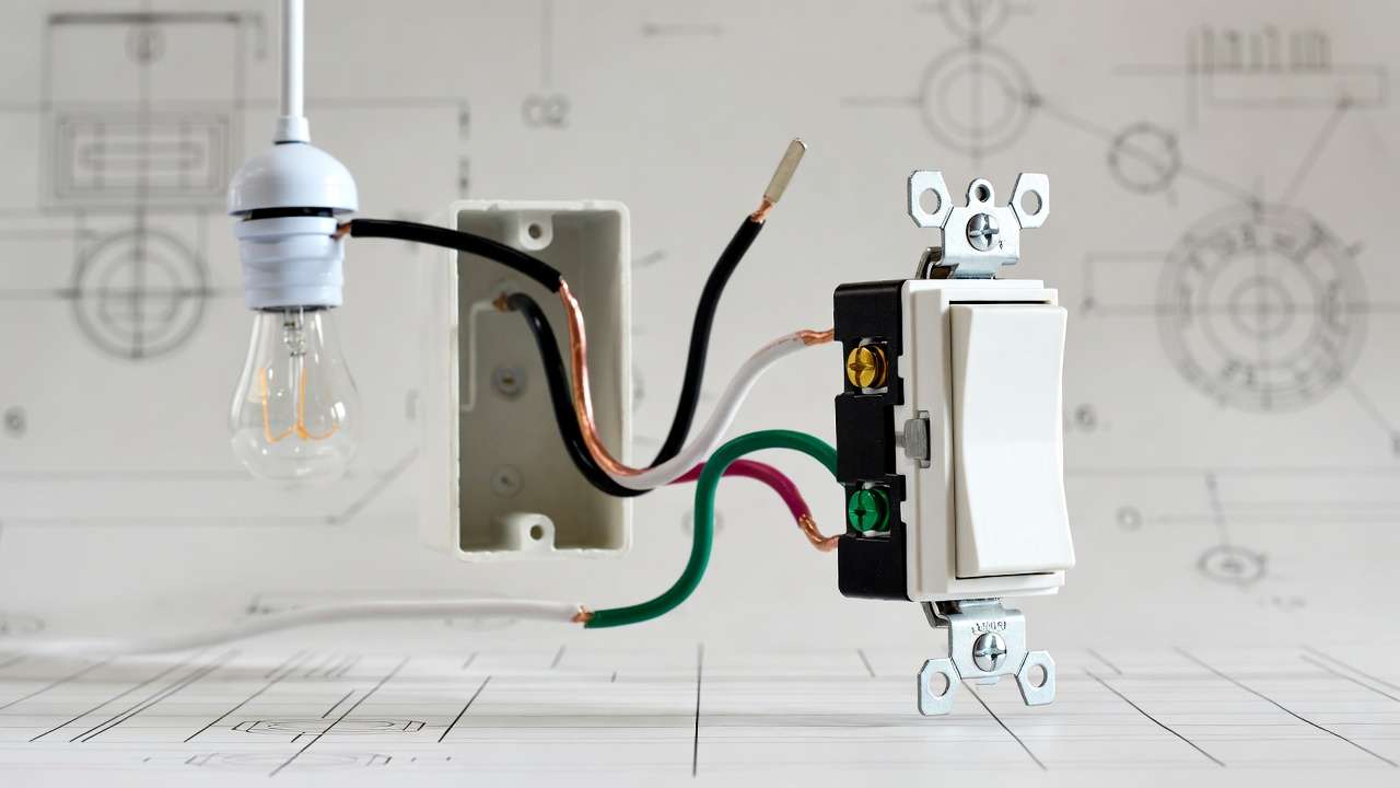
Power to light first (switch loop):
- Hot from panel to fixture box.
- White wire (re-marked black) from fixture to switch as switched hot.
- Black wire from switch to fixture as traveler/hot.
Variations: Parallel multiple lights (wire loads in parallel for independent failure).
3-Way Light Switch Wiring Diagram (Control from Two Locations)
Ideal for staircases or long hallways.
- Two 3-way switches with traveler wires (black and red in 14/3 cable) between them.
- Common terminal on first switch connects to incoming hot.
- Common on second switch connects to switched hot to light.
- Travelers cross-connect the brass screws.
- Neutrals tie through; grounds connect.
Power can enter at first switch, light, or middle—diagrams show all for flexibility. Travelers allow either switch to toggle the circuit.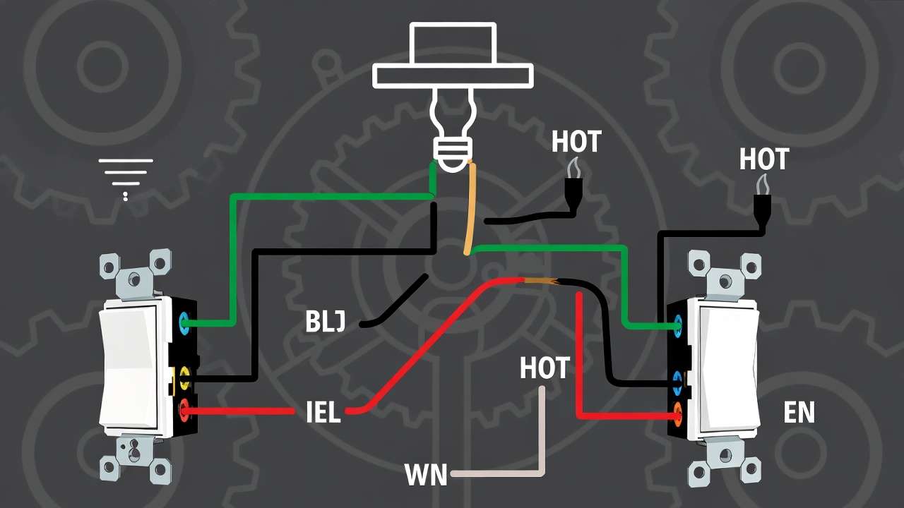
4-Way Light Switch Wiring Diagram (Control from Three+ Locations)
Adds 4-way switches (crossover) between 3-ways.
- Travelers from 3-way to 4-way, then to next.
- 4-way has four terminals: two input travelers, two output.
- Flipping any switch changes state.
Advanced Variations
- Double switches: Two independent single-pole switches in one box (separate circuits or loads).
- Dimmer switches: Require neutral for many models; connect hot to line, load to switched, neutral to neutral.
- Smart switches: Often need neutral; integrate with home automation for mechanical system controls.
Step-by-Step Installation Guide Using Wiring Diagrams
Safety is non-negotiable—electricity doesn’t forgive errors.
Safety First – Always Turn Off Power
- Locate breaker; turn off and lock/tag out.
- Use non-contact tester at switch and fixture—verify no voltage.
- Double-check with multimeter if unsure.
Preparing the Box and Wires
- Remove old switch cover; inspect for damage (e.g., aluminum wiring requires special handling).
- Strip wires ¾ inch; form hooks for screw terminals.
- Use pigtails for multiple connections to reduce box fill.
Wiring a Single-Pole Switch – Detailed Steps
- Connect incoming hot (black) to brass screw.
- Connect outgoing switched hot to other brass screw.
- Connect neutrals together (not to switch).
- Connect all grounds (pigtail to switch ground screw).
- Tuck wires neatly; secure switch; test after powering on.
Common mistake: Backstabbing (push-in terminals)—avoid; use screw terminals for reliability.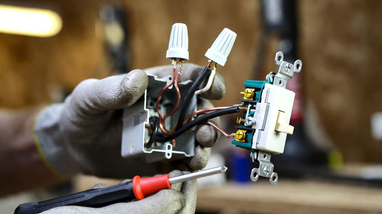
Wiring a 3-Way Switch Setup
- Identify travelers (continuity test or color).
- Connect incoming hot to common on first switch.
- Travelers to brass screws on both switches.
- Common on second to light hot.
- Test toggling from both ends.
Tips for Clean, Code-Compliant Work
- Calculate box fill (NEC limits wires per box size).
- Use proper wire nut sizes; twist tightly.
- Secure cables within 8 inches of box.
How to Read and Interpret Any Light Switch Wiring Diagram
Symbols and Notations Explained
- Switch: Zigzag line or “S”.
- Light: Circle with “X” or bulb symbol.
- Ground: Triangle or line to earth.
- Hot: Solid line; neutral: dashed or marked.
- Line diagrams show flow; pictorial show physical layout.
Troubleshooting with Diagrams
- No power: Check breaker, hot at switch.
- Won’t turn off: Reversed travelers in 3-way.
- Flickering: Loose connections—tighten or re-wire.
- Use diagram to trace path.

Expert Insight: Engineering Perspective
In mechanical systems, consider voltage drop (use thicker wire for runs >100 ft), load calculations (LEDs vs. incandescent), and integration (e.g., relay controls for high-power machinery lighting). Reliable wiring prevents system failures in prototypes or facilities.
Safety Tips and Common Mistakes to Avoid
Electrical work carries inherent risks, but following proven safety practices dramatically reduces them. As a mechanical engineer who has designed and troubleshot countless electromechanical systems, I emphasize that safety is not optional—it is the foundation of reliable performance.
Top Safety Practices
- Never work live: Always confirm zero voltage with a reliable non-contact tester at multiple points (switch terminals, fixture, exposed wires).
- Use GFCI protection when working near water sources (bathrooms, kitchens, outdoors) or during testing.
- Wear appropriate PPE: Insulated gloves rated for 1,000V, safety glasses, and non-conductive footwear.
- Label the breaker: Clearly mark the circuit you’re working on to prevent accidental re-energization.
- Inspect wires carefully: Look for signs of overheating (discolored insulation), brittle cloth-covered wiring (common in pre-1960s homes), or aluminum branch wiring (requires special CO/ALR devices and anti-oxidant compound).
- Follow box fill rules: NEC Article 314 limits how many wires and devices can fit in a box to prevent overheating and arcing.
- Secure all connections: Loose screws or poorly twisted wire nuts are the #1 cause of arcing faults and fires.
The 10 Most Common (and Dangerous) Mistakes
- Failing to turn off power at the breaker and verify with a tester.
- Connecting neutral to a switch terminal instead of hot.
- Reversing travelers in a 3-way setup, causing the light to stay on in one position.
- Using backstab (push-in) connections instead of screw terminals—backstabs are notorious for loosening over time.
- Not connecting the ground wire to the switch (many plastic switches have a green screw—use it).
- Overloading a 15A lighting circuit with high-wattage incandescent bulbs or heaters (stick to LED for modern loads).
- Ignoring neutral requirements for smart dimmers or occupancy sensors—most new models will not function without it.
- Leaving exposed wire strands outside wire nuts or terminals.
- Not securing NM cable within 8 inches of the box entry (NEC 314.17).
- Attempting complex wiring (4-way, multi-gang, or old knob-and-tube) without sufficient experience.
When to Stop and Call a Licensed Electrician
- You discover aluminum wiring.
- The home has knob-and-tube or cloth-insulated wiring.
- You’re working in a commercial/industrial setting with higher voltages or three-phase power.
- The circuit repeatedly trips even after correct wiring.
- You’re unsure about any part of the existing installation.
Following these guidelines aligns with NEC requirements and significantly lowers risk.
Frequently Asked Questions (FAQs)
Here are answers to the questions most frequently asked by readers, DIYers, and engineers alike.
1. Can I use the same light switch wiring diagram for LED, CFL, or smart bulbs? Yes, the wiring diagram remains identical. The switch controls power to the fixture regardless of bulb type. However, some older dimmers are incompatible with LEDs—always check compatibility charts.
2. What’s the difference between a 2-way and a 3-way switch? Terminology varies by region. In the US, a “3-way” switch controls a light from two locations (two switches). In some countries (e.g., UK), “2-way” means the same thing. Always look at the switch terminals: a single-pole has two brass screws + ground; a 3-way has three brass screws (one common, two travelers) + ground.
3. Do modern light switches require a neutral wire? Traditional single-pole and 3-way switches do not require a neutral. However, most smart switches, Wi-Fi dimmers, occupancy sensors, and many decorator-style dimmers do require a neutral to power their internal electronics.
4. How do I convert a single-pole setup to 3-way control? Run 14/3 cable between the two switch locations. Replace the single-pole with two 3-way switches. Connect travelers between the brass screws, incoming hot to one common, and switched hot from the other common to the light.
5. Is this wiring compliant with the latest electrical codes? The configurations shown follow NEC 2023 guidelines (and are backward-compatible with earlier editions still in use). Always verify with your local authority having jurisdiction (AHJ), as amendments are common.
6. Why does my light flicker or buzz with a dimmer? Common causes: incompatible bulbs (use dimmable LEDs), loose neutral connection, undersized wire for the run length, or a defective dimmer. Replace bulbs first, then check connections.
7. Can I wire two lights to one single-pole switch? Yes—wire the lights in parallel. Connect the switched hot to both fixtures, and connect both neutrals and grounds together.
8. What if I have a switch with four terminals but it’s not labeled 4-way? Most 4-way switches have four terminals (two pairs). If unsure, use a multimeter in continuity mode to identify which terminals connect when the toggle is flipped.
9. How do I safely dispose of an old mercury-containing switch? Some very old dimmers contain mercury. Treat them as hazardous waste—check local recycling centers or household hazardous waste collection events.
10. Can I use this guide for industrial or 277V lighting circuits? The principles are similar, but 277V commercial lighting uses different wire colors, higher-rated devices, and stricter code rules. Consult a licensed electrician for anything above residential 120V.
Conclusion
Mastering light switch wiring diagrams equips you with the knowledge to install, troubleshoot, and maintain lighting circuits safely and efficiently—whether you’re upgrading a home, integrating controls into a mechanical prototype, or ensuring reliable operation in a facility.
Key takeaways:
- Always prioritize safety: verify power off, use proper tools, and follow NEC guidelines.
- Start with single-pole basics before tackling 3-way and 4-way configurations.
- Read diagrams methodically—trace the current path from source to load.
- Apply an engineering mindset: consider load, voltage drop, system integration, and long-term reliability.
With this guide, you now have a more comprehensive resource than most online tutorials provide—one that bridges practical DIY needs with professional engineering insight.
If you’re working on an electromechanical project, HVAC control upgrade, or simply replacing switches in your home, apply these steps confidently. Have questions about a specific setup or want guidance on integrating switches into larger control systems? Drop a comment below—I read and respond to every one.
For more in-depth mechanical and electromechanical content, explore related articles such as:
- Electrical Basics Every Mechanical Engineer Should Know
- Wiring Control Relays for Automated Machinery
- Voltage Drop Calculations for Long-Run Circuits
Stay safe, stay precise, and keep building.