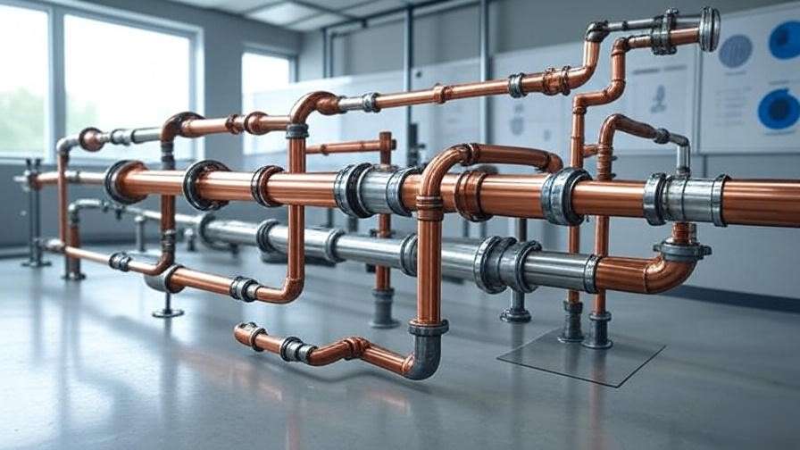
A high-pressure steam line in a processing plant begins to vibrate excessively during startup. Within weeks, fatigue cracks appear at unsupported bends, welds start leaking, and the facility faces an unplanned shutdown costing tens of thousands of dollars per day. The root cause traced back to a single decision: the wrong pipe clamp clamps were selected and installed too rigidly, turning thermal expansion into destructive stress instead of allowing controlled movement.
Pipe clamp clamps—more commonly referred to simply as pipe clamps—are among the most critical yet frequently under-engineered components in any piping system. They do far more than “hold the pipe in place.” Properly chosen and installed pipe clamps control deadweight loads, accommodate thermal growth and contraction, dampen vibration, resist seismic and wind forces, prevent excessive sag, reduce transmitted noise, and protect against galvanic corrosion. When selected incorrectly or installed improperly, they become the weak link that initiates pipe stress failures, support fatigue, insulation damage, and even catastrophic incidents.
As mechanical engineers who have designed, analyzed, and commissioned piping systems in power plants, refineries, HVAC installations, and industrial facilities for over two decades, we treat pipe clamps as precision-engineered elements governed by MSS SP-58, MSS SP-69, ASME B31.1/B31.3, and seismic provisions of ASCE 7 / IBC. This comprehensive guide goes well beyond generic hardware-store advice. We explain:
- Why “pipe clamp clamps” appears in searches (and what it really means)
- Detailed classification of clamp types with engineering rationale
- Load, thermal, vibration, and environmental selection criteria
- Step-by-step installation procedures with torque values and alignment checks
- Common failure modes with root-cause analysis
- Advanced design strategies used in critical piping networks
Whether you are sizing supports for a new chilled-water riser, retrofitting vibration-prone lines in a data center, or preparing seismic bracing calculations, this article provides the depth and practical insight needed to make informed, code-compliant decisions that extend system life and reduce maintenance costs.
What Are Pipe Clamp Clamps? Definition and Engineering Role
Pipe clamps are mechanical devices that encircle a pipe (with or without insulation) and transfer its weight, dynamic forces, and restraint requirements to a supporting structure—typically a beam, column, wall bracket, channel strut, or floor stand.
Core components usually include:
- One or two clamp halves (band, strap, or yoke style)
- Bolts, nuts, and washers (frequently hex-head or carriage bolts)
- Optional cushion/liner (EPDM, neoprene, polyurethane, or PTFE)
- Optional shield or saddle for insulated lines
- Attachment hardware (bolt-through base, threaded rod, or strut nut)
Key functional distinctions (frequently confused in practice):
- Pipe clamps → primarily circumferential restraint and vertical support
- Pipe hangers → suspension from above (clevis, band, roller, spring)
- Pipe supports → broad category including bases, shoes, saddles, stands
- Guides & anchors → directional restraint or full fixation
The redundant phrase “pipe clamp clamps” often appears in product searches and e-commerce listings as users attempt to distinguish clamps from straps, clips, or hangers. In engineering specifications, we simply use “pipe clamp” or the specific MSS type designation.
From a mechanical engineering standpoint, pipe clamps serve four primary roles:
- Deadweight support — prevent excessive sag (per allowable deflection limits, typically L/240 or ¼ inch maximum)
- Thermal movement accommodation — permit axial expansion/contraction while controlling lateral displacement
- Vibration and dynamic load control — limit transmitted vibration (per ISO 10816) and resist occasional shocks
- Restraint against external forces — wind, seismic, water hammer, relief valve thrust
Incorrect clamping can lead to:
- Pipe ovality or crushing
- Insulation compression and thermal bridging
- Fatigue cracking at welds or bends
- Excessive stress intensification
- Noise transmission into building structures
Main Types of Pipe Clamp Clamps
Understanding the engineering differences between clamp families is essential for correct application.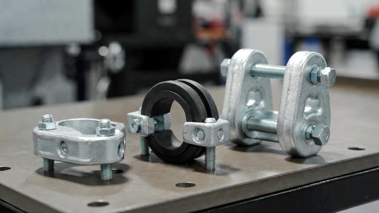
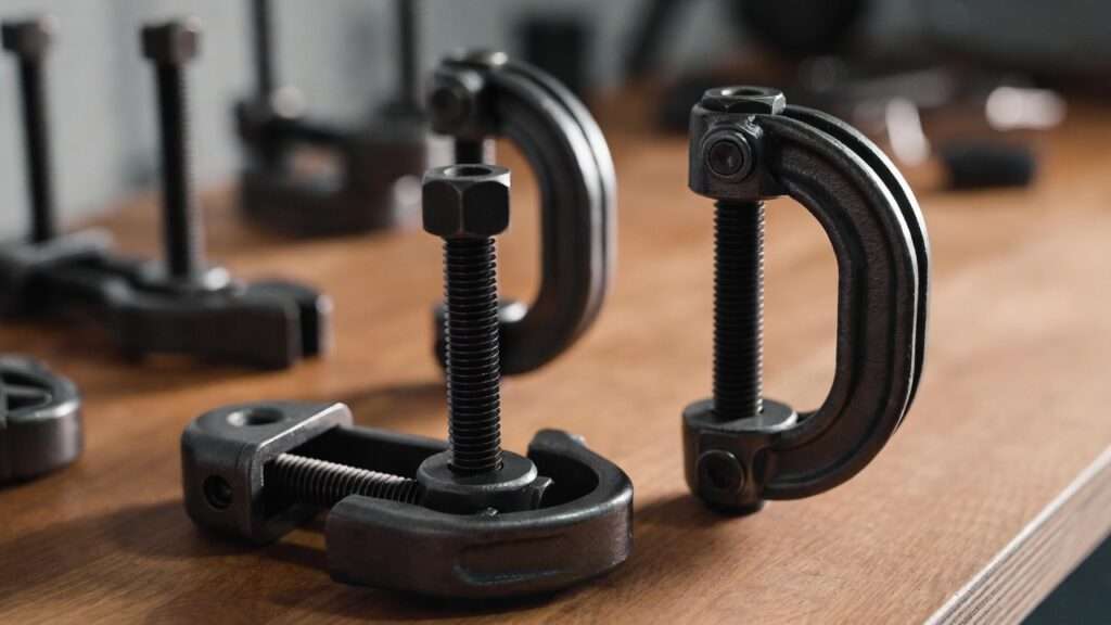
1. Standard / Two-Bolt Pipe Clamps Most common general-purpose clamp. Two semicircular halves joined by two bolts. Available lined or unlined. Typical load range: 500–3,000 lb depending on size and material. Best for: Plumbing, HVAC ductwork support, light process piping at moderate temperatures.
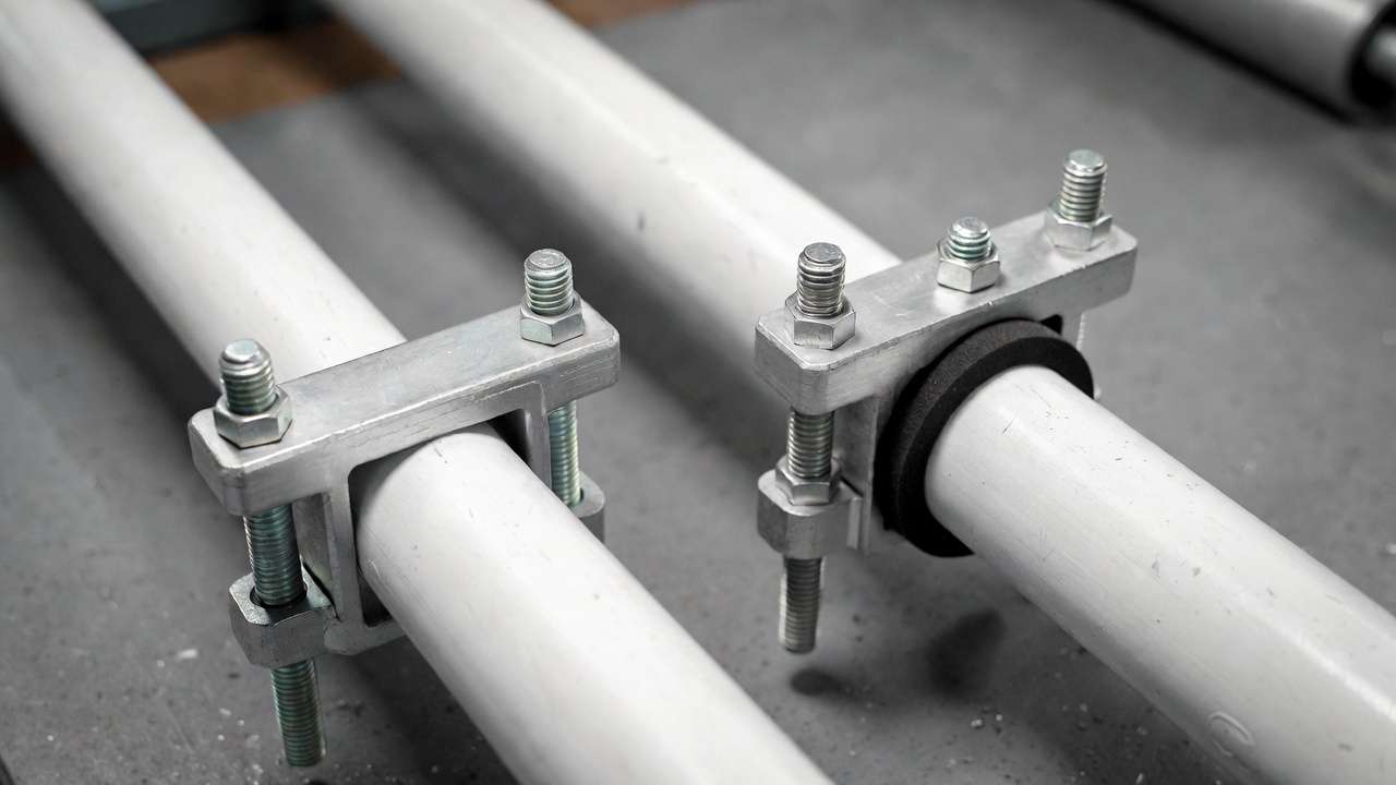
2. Cushioned / Lined Pipe Clamps Identical geometry but fitted with a resilient liner (usually ⅛″–¼″ thick EPDM, neoprene, or silicone). Primary functions: vibration isolation, galvanic separation (copper/stainless to carbon steel), noise reduction, protection of thin-wall or coated pipe. Critical in: Chilled-water lines, domestic hot/cold water, data-center cooling, medical gas.
3. Heavy-Duty / Three-Bolt Pipe Clamps Three-bolt design distributes load more evenly across the pipe circumference, reducing point contact stress. Higher load ratings (up to 10,000+ lb for larger sizes) and better high-temperature performance. Specified when: Pipe OD > 12″, steam/high-temp service, heavy insulation loads.
4. U-Bolt Pipe Clamps U-shaped bolt passing around the pipe with a flat plate and two nuts. Excellent for axial restraint and seismic/wind bracing. Frequently paired with: structural steel, concrete embeds, or base plates.
5. Riser Clamps Two-bolt vertical clamp with extended ears or shear lugs that bear directly on the structure. Engineered to carry full riser weight (pipe + fluid + insulation) in compression. Common in: Vertical risers in high-rise buildings, fire-protection standpipes.
6. Strut / Channel-Mounted Clamps Single-bolt or quick-connect clamps designed to attach directly to Unistrut-style channel. Advantages: rapid field installation, modular reconfiguration, high adjustability. Widely used in: Mechanical rooms, data centers, clean rooms.
7. Specialty Pipe Clamps
- Repair / emergency clamps (split-sleeve style for leak containment)
- Insulated pipe clamps with load-distribution shields
- Welding alignment clamps (temporary during fabrication)
- Hold-down clamps (prevent uplift in seismic zones)
(Suggested visual: Annotated comparison diagram showing cross-sections and load paths of the seven main types.)
Pipe Clamp Clamps Explained: Types, Selection, and Secure Installation in Mechanical Systems (Continued from previous section)
Comparison of Pipe Clamp Types: Which to Choose?
Selecting the correct pipe clamp requires balancing load capacity, environmental conditions, movement requirements, vibration sensitivity, and budget. Below is a practical comparison table engineers use during preliminary design or field retrofits:
| Type | Typical Load Capacity (lb) | Vibration Damping | Temperature Range (°C) | Best For | Relative Cost | Key Engineering Notes |
|---|---|---|---|---|---|---|
| Standard Two-Bolt | 500–3,000 | Low | –20 to +150 | General plumbing, light HVAC | Low | Basic vertical support; minimal restraint |
| Cushioned / Lined | 500–2,500 | High | –40 to +120 | Chilled water, copper/stainless, noise-sensitive areas | Medium | Prevents galvanic corrosion & noise transmission |
| Heavy-Duty Three-Bolt | 2,000–12,000+ | Medium | Up to +400 | Steam, high-temp process piping | High | Better load distribution; MSS SP-58 compliant |
| U-Bolt | 1,000–8,000 | Low | Wide | Axial restraint, seismic/wind bracing | Low–Medium | High friction when tight; calculate slip force |
| Riser Clamp | 5,000–30,000+ | Medium | High | Vertical risers in high-rise buildings | Medium | Transfers axial load via shear lugs |
| Strut / Channel-Mounted | 500–4,000 | Medium | –20 to +150 | Modular mechanical rooms, data centers | Medium | Fast installation; high adjustability |
| Insulated Pipe Clamp + Shield | Varies by shield | High | Wide | Insulated hot/cold lines | High | Prevents insulation compression & heat bridges |
Quick selection flowchart logic (mental model engineers use):
- Is the pipe insulated? → Use shield + cushioned or insulated clamp.
- Is vibration/noise a concern? → Prioritize lined/cushioned clamps.
- High temperature (>150°C) or heavy load? → Heavy-duty three-bolt or custom fabricated.
- Vertical riser carrying full fluid weight? → Riser clamp.
- Need quick modular install in mechanical room? → Strut-mounted.
- Seismic or wind restraint required? → U-bolt or hold-down + engineering analysis.
Selection Criteria: Engineering Guidelines for Pipe Clamp Clamps
Proper clamp selection follows a systematic process aligned with ASME B31 codes and MSS standards.
1. Pipe Size, Material, and Insulation Status Match clamp inside diameter to pipe OD (including insulation thickness + shield if used). Avoid direct metal-to-metal contact on dissimilar metals (copper to steel) — use lined clamps or neoprene isolators. For insulated lines, always use load-bearing shields (MSS Type 39 or 40) to prevent crushing foam or fiberglass.
- Deadweight: pipe + fluid + insulation + valves/fittings.
- Use spacing tables from ASME B31.1 (power piping) or B31.3 (process piping): typical 8–12 ft for 2–6 inch lines, reduced for larger/heavier pipes.
- Deflection limit: usually L/240 or ¼ inch max sag between supports.
- Include occasional loads: wind, seismic (ASCE 7), water hammer.
3. Thermal Movement & Expansion Calculate axial growth: ΔL = α × L × ΔT (α ≈ 6.5–7.0 × 10⁻⁶ in/in/°F for carbon steel; higher for copper/PVC) Clamps must allow sliding (low-friction liners) or guide movement without binding.
4. Vibration and Dynamic Considerations
- Avoid natural frequency coincidence with equipment excitation (pumps, compressors).
- Use lined clamps to increase damping ratio.
- For severe vibration, combine with spring isolators or flexible connectors.
5. Environmental & Corrosion Factors
- Indoor dry: electro-galvanized carbon steel sufficient.
- Outdoor/wet/corrosive: 304 or 316 stainless steel.
- Chemical exposure: epoxy-coated or special alloys (Hastelloy, Monel for extreme cases).
6. Code & Standard Compliance
- MSS SP-58: Types & terminology
- MSS SP-69: Pipe hanger & support selection
- IBC/ASCE 7: Seismic bracing requirements
- NFPA 13: Fire sprinkler pipe support rules
Step-by-Step Guide: Proper Installation of Pipe Clamp Clamps
Correct installation prevents 70–80% of premature clamp-related failures.
Tools Required
- Calibrated torque wrench
- Level, plumb bob, laser alignment tool
- Anti-seize compound (for stainless bolts)
- Wire brush, degreaser
- Pipe rollers/guides if thermal movement expected
General Installation Procedure
- Mark support locations per engineering drawings or code spacing tables.
- Install structural attachment (beam clamp, concrete anchor, strut channel) and verify load rating.
- Position clamp halves around pipe (ensure liner is correctly oriented if present).
- Insert bolts and hand-tighten nuts evenly (cross-pattern).
- Align pipe horizontally/vertically; check for binding or misalignment.
- Torque bolts to manufacturer specification (typical values below):
- ⅜″ bolts: 15–25 ft-lb
- ½″ bolts: 40–60 ft-lb
- ⅝″ bolts: 80–120 ft-lb
- Install any required guides, shields, or expansion gaps.
- Verify 1/16–1/8 inch gap between clamp halves (prevents over-compression).
Type-Specific Installation Tips
- U-bolt: Torque nuts alternately; leave slight gap under plate for thermal growth.
- Riser clamp: Weld or bolt shear lugs to structure; ensure full bearing contact.
- Cushioned clamp: Do not over-compress liner (max 25% compression).
- Strut-mounted: Use channel nuts; tighten to 20–30 ft-lb.
Post-Installation Checks
- Visual inspection for gaps, misalignment, or liner extrusion.
- Tap test for loose bolts.
- Vibration baseline reading if critical system.
Common Mistakes and Engineering Solutions
- Over-tightening → Pipe ovality, liner extrusion, stress corrosion. Solution: Always use calibrated torque wrench; follow MSS torque tables.
- Incorrect spacing → Excessive sag, high bending stress. Solution: Use code tables or finite element analysis for non-standard layouts.
- Missing liners on dissimilar metals → Galvanic corrosion. Solution: Specify lined clamps or dielectric barriers.
- Rigid clamping in hot lines → Thermal binding and anchor point overload. Solution: Allow sliding (low-friction pads) or use rollers.
- Ignoring seismic requirements → Failure during earthquake. Solution: Perform seismic analysis per ASCE 7; add lateral restraints.
Advanced Tips from Mechanical Engineers
- Clamp spacing calculation example: For 6-inch Sch 40 steel pipe (water-filled), use approximate formula: spacing ≈ √(EI / w) × constant, where E = modulus, I = moment of inertia, w = weight per foot. Typical result: 10–12 ft max.
- Combining clamps with variable springs for large vertical risers with significant thermal growth.
- Seismic qualification: Use OSHPD pre-approved clamps or perform shake-table certification for critical facilities.
- Predictive maintenance: Annual torque re-check + visual inspection for wear, corrosion, or liner degradation.
- Noise & vibration mitigation: Combine lined clamps with acoustic isolators and flexible connectors upstream/downstream of pumps.
Frequently Asked Questions (FAQs)
What is the difference between pipe clamps and pipe hangers? Pipe clamps encircle and support from below or sides; hangers suspend from above (clevis, band, spring).
How do I choose pipe clamp clamps for insulated pipes? Use insulated clamps with load-bearing shields to prevent crushing insulation and creating thermal bridges.
What torque should I apply to pipe clamp bolts? Follow manufacturer tables; common ranges: 15–25 ft-lb for ⅜″, 40–60 ft-lb for ½″. Always use calibrated wrench.
Are stainless steel pipe clamps necessary for outdoor use? Recommended in corrosive or coastal environments; 304/316 grades resist rust far better than galvanized.
How do pipe clamp clamps prevent vibration damage? Lined clamps absorb energy; proper spacing avoids resonance; additional isolators needed for severe cases.
Can I use the same clamp type for seismic restraint? No—seismic requires specific hold-down, U-bolt, or braced configurations per ASCE 7 analysis.
Conclusion
Pipe clamp clamps are far more than simple hardware—they are engineered components that directly influence the safety, reliability, longevity, and performance of any piping system. By understanding the types, applying rigorous selection criteria, following precise installation procedures, and avoiding common pitfalls, engineers and installers can dramatically reduce failures, maintenance costs, and operational risks.
Next time you specify, procure, or install pipe supports, treat clamps as precision elements rather than commodity items. The small extra effort in design and execution pays dividends in system uptime and safety.
Have a challenging piping support scenario? Share it in the comments—we review and respond to every engineering question.
For more advanced mechanical engineering topics—including piping stress analysis, vibration isolation strategies, seismic bracing design, and support optimization—explore the rest of Mech Tips Zone.
Stay structurally sound, Mech Tips Zone Team